Hi,
if you wind an P-P output transformer and decide to part the primary winding into four pieces, interleaved by three secondary winding parts, there are two ways at least to do so:
- You divide the whole number of primary turns by four and connect the four parts in series,
- or you divide by two and connect two parts each in parallel to form one half of the primaries.
The three secondary parts are connected in parallel in both versions.
Which option is to be preferred, and why?
Best regards!
In part it depends on the number of turns in the primary. I there are a low number of turns, then the parallel method may have advantages using smaller wire size.
If there are a large number of turns in the primary, then the series method has an advantage of reducing the total number of turns to be wound.
1/6 : 1/3 : 1/3 : 1/6
Making the outer an inner layers 1/2 of the middle layers is a recomended way in a number of texts I've seen.
If there are a large number of turns in the primary, then the series method has an advantage of reducing the total number of turns to be wound.
1/6 : 1/3 : 1/3 : 1/6
Making the outer an inner layers 1/2 of the middle layers is a recomended way in a number of texts I've seen.
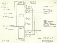
As I hope you probably already know, everything one does in output transformer design is a trade off. A compromise. To gain something, you must sacrifice something. These trade offs may not always be apparent, but they are there none the less. Size, weight, cost, efficiency, frequency response, leakage inductance, distributed capacitance, wire size, winding style (single or bifilar), insulation type, core material, sealing and more just to name a few. There is not a simple direct answer to your question because it all depends on the above choices. Below is a design choice for a P-P transformer with screen taps.
Attachments
Thanks to both of you!
Your suggestions show series connection of the primary parts, the way I'd also prefer for some reasons: In thinner wires the laquer insulation's part of total cross-section generally is larger, so the copper part in a given winding space is smaller, leading to more ohmic losses. And, last but not least, if one doesn't own a winding machine with a precise counter, but tries to wind manually instead, the number of turns in every part is not that important as it has to be if these parts are in parallel.
Best regards!
Last edited:
- Status
- Not open for further replies.