AndrewT, this is the information i asked akis for but never got an answer it is essentialy what you are telling him now.
akis, I have never seen a power amp like this. what are the rail voltages, how much power are you trying to get in 1R? how much gain does this amp have, closed loop? do you have a schematic that shows the entire amp design excluding the power supply?
akis, I have never seen a power amp like this. what are the rail voltages, how much power are you trying to get in 1R? how much gain does this amp have, closed loop? do you have a schematic that shows the entire amp design excluding the power supply?
AndrewT, this is the information i asked akis for but never got an answer it is essentialy what you are telling him now.
akis, I have never seen a power amp like this. what are the rail voltages, how much power are you trying to get in 1R? how much gain does this amp have, closed loop? do you have a schematic that shows the entire amp design excluding the power supply?
I was sure I did answer but here it is again?
Rails are 10.5V to 13V each. Trying to push 8V peak into 1R load at 200KHz, fixed frequency. There is no gain, as you can see on the schematic. It is just a current buffer stage.
The circuit has been built and works fine until the point where we (a) lower the load close to 1R AND (b) approach the rails too much (a little over 8V peak).
For example the built device works fine with +/-12V voltages, 8V peak into 1R load, no probs.
Now try to lower the rails to +/-11V and you get instantaneous thermal runaway. Curable with lowering the bias, which was fixed and without thermal compensation.
Also curable with increasing the rails - but it is running off a battery so we do not have many luxuries. We cannot afford to sacrifice rail voltage, we cannot afford to throw away power, and we do not have space either, so it is not easy to mount 8 output transistors and heatsink(s) into the case (but am trying).
The reason why using two parallel transistors is exactly this : how close to the rails can we go and how high a load can we support. But it seems I need to increase the 0.1R emitter resistors with something like 0.22R and then add a few more transistors to compensate.
My latest design adds another 4 output transistors and drivers. That will allow me to increase the emitters to something like 0.22R and hopefully will allow me to reach close to the rails.
I tried the LM3886 again and I can re-confirm it also has great problems into 1R load. The negative portion of the curve requires a lot of headroom, much more than my device. It also distorts and oscillates the bottom of the curve at those loads.
Edit: actually I did answer at #17 🙂
Last edited:
AndrewT, I was just saying that i asked akis for the info i had shown in my message to help calculate the information you toched on in this message.Find the minimum Rs that ensures stability of the output stage at the voltages and gains you require. Then add multi-parallel output stages to deliver the current you need.
Increasing the emiter resistors is a good idea.
Adding output pairs is a good idea.
But if you want to track the temperature,
the only way to do it is to monitor the DRIVER transistor temperatures.
Use common sense; there is 83.1R which is shorted to ground with a 600mW device (with a certain frequency and duty).
How hot will that device become and how FAST, and how can it ever be compensated for, if the monitor is on the output device?
The output device will blow up in no time with a less than 10C internal temperature rice in the driver - make that, a LOT less...
We must fix the cause, not the consequence.
Yes the temperature rise on the drivers is maximum 5-10C with no heatsinks, while the output transistors were at 70C (a rise of 45C). Simulation shows 70mW per driver.
Since the problem goes away with simply increasing the supply rail by half a volt or so, I
believe it also has to do with switching the transistors off once they are on, the more close to the rails you are the more "on" the transistors are and the harder it is to switch them off. There is a term for this I have seen somewhere, but I have not read any practical design recommendations. If you know what I am talking about maybe we can improve on this area? I would not even know how to calculate it.
Hi Akis,
The term you are looking for is saturation This is where (for an NPN transistor) the base is higher than the emitter but the the collector is not higher than the base. It takes a long time for a device in saturation to switch off and meanwhile both output devices are on leading to a short circuit, high current and thermal runaway.
My blog
Consort3's Blog | Just another WordPress.com weblog
1) CFp output stage you need to monitor temp on the drivers
2) if drivers are in a common heatsink the all thing will work better ( separated though per chanel )
3) If outputs are also in a common heat sink will also work better ( separated though per chanel )
4) attaching all these transistors as seen in post #9 to the drivers heatsink will be a faital error you will only need to thermal compensate the drivers and the Vbe multiplier
5) ventilator will only complicate bias settings and temperature monitor It is mandatory to preserve that the Vbe multiplier is OUTSIDE the air flow ...Circuit will have to be stabilized before ventilation added ...If one is needed and finally added it WILL ONLY HAVE TO BLOW OUTPUTS
6) Adding an extra pair of outputs will only complicate things and add stability problems in the circuit ...( ppl have to stop thinking EFP when talk about this circuits )
7) increasing "output" resistors will add stability but it will effect performance up to a point
8) If manage after all with the thermals you may try other types of drivers of the 2SA family since these ones will play far better than your original choice ( together with the output )
solution will be to redesign the all thing with better output capability ( 2 transistor only remain in the circuit but capable of a bit more power and current ) probably with higher rail voltage and more headroom ....Still if the schematic is as seen with small heatsinks separated on board with a ventilator blowing at them the chances for a thermally stable circuit ( that beyond temperature will have performance issues) is a total zero ...
Kind regards
Sakis
Last edited:
@consort: definitely saturation since adding about 200mV at the rails resolves the problem
@sakis: many good points.
The fan is needed because there is space limitation inside small case.
Why not add more transistors to handle the load, reduce losses, and increase emitter resistors?
Which 2SA transistors did you have in mind? Considering the power spent on drivers is around 60mW each.
I have taken some pictures so you can see where I am now.
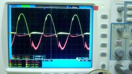
You can see the tightness of the case, 4 output transistors mounted back to back and the heatsinks linked together. The drivers are not mounted on anything and with or without airflow from the fan they are at a steady 25C-30C. Without fan output transistors go over 70C after a few minutes. On the scope you can see input (yellow) and output curves. With very little bias there is harmonic distortion (bottom of curve) but that cures itself on load as the bias increases due to heat. The input wave is a little over 8V peak while the rails must be at over 11.5V to handle the loads.
@sakis: many good points.
The fan is needed because there is space limitation inside small case.
Why not add more transistors to handle the load, reduce losses, and increase emitter resistors?
Which 2SA transistors did you have in mind? Considering the power spent on drivers is around 60mW each.
I have taken some pictures so you can see where I am now.
You can see the tightness of the case, 4 output transistors mounted back to back and the heatsinks linked together. The drivers are not mounted on anything and with or without airflow from the fan they are at a steady 25C-30C. Without fan output transistors go over 70C after a few minutes. On the scope you can see input (yellow) and output curves. With very little bias there is harmonic distortion (bottom of curve) but that cures itself on load as the bias increases due to heat. The input wave is a little over 8V peak while the rails must be at over 11.5V to handle the loads.
Attachments

.... You will never make thermal stability with such a design and lay out
.... the ventilator will make things far worst in stability terms
.... Any ""thermal balance"" you manage to achieve will be phantom and it will be only possible to achieve in static conditions steady load and source ( so audio signals is not none of them ... )
If you stay with the circuit as is and after all you will need a vent you need to redesign everything that can be very obviously done , but the design may have the same size but it needs to be designed exactly as a pro amp :
If forced cooling is needed via ventilation the flow of air will only circulate in the output with no temp effect in the rest of the circuit plus that in long term no dust will fill your design
Why not add more transistors to handle the load, reduce losses, and increase emitter resistors?
Cause this is EFP thinking and it is the agenda to get more power from a classic Ab circuit given the fact that rails will be increased
In a CFP circuits there is no output transistors signal is coming from the drivers and the external transistor is working only according to the needs of the driver , working as an amplifier for the driver ... That will make the so called output transistor working outside the feedback node , and the thermal compensation ...eventually the transistor is actually working on its own and outside the real amplifier circuit , and if you add more you will make some more current in the output but drive problems may show up together with more active devices in the output working ""out of control""
Made this as simple Greek as it can be done
Kind regards
Sakis
In the repair business we have Monday with a happy hour
Usually we get amplifiers to repair from home use at Monday mornings since those have been playing in a home party at Saturday night ...
The usual costumer statement is :
""It is impossible for me to understand how did i manage to blow the amp since i already had a computer ventilator above it to cool it down """
The answer is given above the costumer was blowing the internals of the amp probably cooling efficiently the board together with it the LTP stages and VAs and the Vbe multiplier ....The vbe cooling down made him think that heatsink temp is low so bias may come up to the normal operation levels ...
That is the quick solution to thermal runaway and blow the amp that other than the above may actually manage without a vent ...
Marvelous !! wasn't it ?
Kind regards
Sakis
Peak current is 8A into 1R load. The two transistors need to pass over 4A each at the peaks. Looking at the beta curves, we would need a 15A-20A transistor to produce a flat gain at 4A!. The transistors I use are only good for 2A and not very hot either.
There is no feedback on my circuit and I presume there are not many amps without feedback. OK, there is local feedback at the emitters and a bit of capacitance at the drivers to stop oscillations, but no global or other feedback of any kind. Therefore the transistors, be that 2 on each side or how many, "run on their own" as you said, but I cannot see this as a problem, ideally they should do as they are told without feedback. 🙂
Anyway, based on the limitations of case size, voltage rails (10.5V) and requirements (8A into a 1R load), I will add one more transistor pair and increase the emitter resistors to 0.15R from 0.1R.
If that does not work still, then I will use larger transistors, like the MJL1302A.
MJ15003/4 have a lot more capability.Peak current is 8A into 1R load..................
If that does not work still, then I will use larger transistors, like the MJL1302A.
A quick update while I am debugging.
I have made a new board using 3 sets of transistors, and the problems are exactly the same as before. The Re are now 0R15 each, used to be 0R10 with two transistors.
The problem is that the circuit works ok and is thermally stable, until I increase the load beyond a certain point. At that point there is a very quick thermal runaway, lasts a few seconds before the bench PSU current limit kicks in. It is not possible to sense this thermally as the heat does not really have time enough to travel outside the transistors' cases.
Funnily enough, if I increase the rails, which ought to make things even worse, the circuit works better. This is weird.
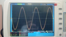
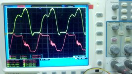
Doing some debugging now and there are two screenshots, taken at a random emitter resistor (there are 6 to choose from). On the first picture the load is around 1.8-2 Ohms and you can clearly see one transistor opening while the other one remains closed. More or less.
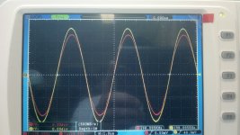
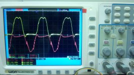
The next picture shows what happens when the load drops to 0.8Ohms or so, the transistors both stop closing as they should, they remain open for more of the cycle than they should and they both "play" into each other, thus consuming a lot of power.
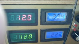
The last picture shows the exact same situation but with rails increased by 1.5V each. As if by magic, no thermal runaway.
If anyone has any new pointers please let me know. My next step will be to try bigger transistors.
I have made a new board using 3 sets of transistors, and the problems are exactly the same as before. The Re are now 0R15 each, used to be 0R10 with two transistors.
The problem is that the circuit works ok and is thermally stable, until I increase the load beyond a certain point. At that point there is a very quick thermal runaway, lasts a few seconds before the bench PSU current limit kicks in. It is not possible to sense this thermally as the heat does not really have time enough to travel outside the transistors' cases.
Funnily enough, if I increase the rails, which ought to make things even worse, the circuit works better. This is weird.
Doing some debugging now and there are two screenshots, taken at a random emitter resistor (there are 6 to choose from). On the first picture the load is around 1.8-2 Ohms and you can clearly see one transistor opening while the other one remains closed. More or less.
The next picture shows what happens when the load drops to 0.8Ohms or so, the transistors both stop closing as they should, they remain open for more of the cycle than they should and they both "play" into each other, thus consuming a lot of power.
The last picture shows the exact same situation but with rails increased by 1.5V each. As if by magic, no thermal runaway.
If anyone has any new pointers please let me know. My next step will be to try bigger transistors.
Attachments
You're running into cross-conduction or "shoot-through", as it's called in Class D. Try higher driver current.
So I take it you have 3 CFPs in parallel? One CFP with multiple transistors may be worth a shot.
People are not generally expecting full power output at almost 200 kHz in audio, so you may want to consult with the RF crowd as well.
So I take it you have 3 CFPs in parallel? One CFP with multiple transistors may be worth a shot.
People are not generally expecting full power output at almost 200 kHz in audio, so you may want to consult with the RF crowd as well.
Last edited:
You're running into cross-conduction or "shoot-through", as it's called in Class D. Try higher driver current.
So I take it you have 3 CFPs in parallel? One CFP with multiple transistors may be worth a shot.
People are not generally expecting full power output at almost 200 kHz in audio, so you may want to consult with the RF crowd as well.
OK so now I know that there is a known problem and there are multiple people in that thread that know exactly what it is even though I do not understand their suggestions and the OP was switching between real design and simulation thus confusing the issue.
I tried increasing the driver current, no change. I do not understand what you mean by "one CFP with multiple transistors" ?
I have started a new thread entitled "Cross-conduction with complimentary pairs"
- Status
- Not open for further replies.
- Home
- Amplifiers
- Solid State
- output stage thermal stabilisation