Hi Andrew,
On the simulation distortion increases heavily (from 0.070% to 0.2%) when I add base stoppers to the drivers, even small values. On the simulation I can clearly see cross-conduction, when it is present, but I cannot see the oscillations that occur under load (or not).
On the PCB the base stopper value that eliminated oscillations was 15R. I tried 1R, 1R5 and 10R and it was not enough. The price to pay is that the drivers now do more work than before, and the transistor pair's overall beta has dropped considerably.
Because the Sziklai pair's beta is lower, the driver current is not as "constant" as it would be without the base stopper in place. Although the drivers now get hotter than before, maybe as much as 5C-10C in my case, the overall stage is less sensitive to the thermal runaway generally caused by hot drivers. In other words the leverage is smaller now.
I am wondering if in effect what we did was to lower the beta of the pair making it less sensitive to whatever triggers and pressures were causing the oscillations before. But by lowering the beta we giving up some of the advantages of the compund pair, and we decrease the stage's input resistance.
I will try to simulate and calculate the overall beta drop.
Some comments:
The choice of CFP is rather unfortunate for this range of frequency: there is no possibility of active turn-off of the OP by the opposite driver, as in EF.
The CFP is also more touchy regarding stability.
That said, there should be no oscillation even with CFP.
I can see a few possible causes: layout is the first that comes to mind.
Maybe related, this kind of paralleling can create a push-pull oscillator between a pair of paralleled transistors.
Any kind of follower tends to synthetize a negative impedance at the input, and this can also create a sort of Colpitts oscillator, in particular if the input sees an inductive component (wiring?).
The CFP topology probably exacerbates this kind of tendency.
If the emitter resistors are inductive (wirewound), they can also sometimes cause problems.
An alternative to base stoppers is sometimes to place a ferrite bead in the emitters of the drivers. It can also have the opposite effect though....
Maybe related, this kind of paralleling can create a push-pull oscillator between a pair of paralleled transistors.
This is the main reason for base stoppers. And why the "need" for them rarely shows up in a stability analysis. Unless you do a rigorous even/odd mode analysis, with a model accurate to a GHz or so, under large signal conditions.
I have never needed base stoppers in any output stage that did NOT use parallel transistors. I've gotten away without them quite often, but only with EF2 and EF3 with a reasonable number of outputs or with single CFP's operated off low supply voltages.
I have run some simulations to understand better the role of the base stopper.
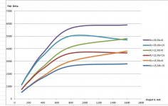
These two graphs show the compund pair's beta vs the output current. Rc is the collector resistor (typically 100R but for HF applications as low as 5.6R) and Rb is the base stopper resistor.
As it can be seen the overall beta of the pair depends heavily upon the collector resistor, the higher the better.
The base stopper resistor lowers the compound pair's beta, as currents increase.
Because we have added the base stopper resistor we have effectively limited how fast the output transistor can close and we have introduced cross-conduction again (at HF).
We then have to lower Rc futher in order to combat cross-conduction.
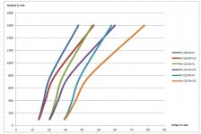
But this now means that the driver transistors are doing more work, as can be seen on the second graph, which shows the current through the drivers against the current of the output devices. As the collector resistor decreases, the drivers have to work more.
These two graphs show the compund pair's beta vs the output current. Rc is the collector resistor (typically 100R but for HF applications as low as 5.6R) and Rb is the base stopper resistor.
As it can be seen the overall beta of the pair depends heavily upon the collector resistor, the higher the better.
The base stopper resistor lowers the compound pair's beta, as currents increase.
Because we have added the base stopper resistor we have effectively limited how fast the output transistor can close and we have introduced cross-conduction again (at HF).
We then have to lower Rc futher in order to combat cross-conduction.
But this now means that the driver transistors are doing more work, as can be seen on the second graph, which shows the current through the drivers against the current of the output devices. As the collector resistor decreases, the drivers have to work more.
Attachments
Thinking in terms of beta is certainly not very helpful: that is true in general, but particularly so in tackling parasitic oscillations.I have run some simulations to understand better the role of the base stopper.
.../...
Think about the (artificial) variations of the apparent beta the resistors cause to the compound: they don't make a lot of sense.
You just have to make sure the transistors receive enough input current under worst case conditions to deliver the required worst case output current; and, of course, the resistors influence these calculations, but going further is misleading, and probably a waste of time.
Stoppers work by compensating negative impedances, and by introducing HF rolloff when combined with the inherent capacitances of semi's, not by reducing beta.
For oscillations to occur, the power gain needs to be >1, and this condition is easily met, even when the effective beta is <1.
Note that stoppers can sometimes aggravate the problem: negative impedances can present themselves under parallel or series guises: with the parallel type, adding a stopper will make thing worse.
Anyway, the main problems reside in the layout, and input or output impedances: even a CFP could be made stable without any stopper or similar band-aid, but migrating towards an EF topology would make many things easier.
Last edited:
Hi, the reason I originally looked at the CFP is because of the praise given on the ESP site (Rod Elliott) and also because I wanted to go as close to the rails as is possible because it is battery powered. I am now using different batteries so I can relax that requirement, maybe. I may also be able to use larger transistors so that I would not need 3 parallel pairs, maybe just one pair would do. I am trying to run some simulations now using the MJL1302A and MJL3281A.
CFP is indeed excellent for audio applications: its accuracy as a follower is significantly better than EF, but unless you go to extraordinary lengths, there is no way to include an active charge extraction system for the formerly active transistor, and under large signal/high frequency conditions, this really is a problem (unless you use extremely fast transistors, but this approach has problems of its own, as you noticed).Hi, the reason I originally looked at the CFP is because of the praise given on the ESP site (Rod Elliott)
Since you use the OP stage "raw", without any other intermediate stage, the awkward input impedance is also a problem.
I have never needed base stoppers in any output stage that did NOT use parallel transistors.
The reason I am using parallel transistors is because I could not, at the time, find a suitable larger transistor to work at HF without cross conduction. For example I am trying now to simulate the combination of D44H11/MJL1302A and there is terrible cross conduction it seems the MJL is so slow.
- Status
- Not open for further replies.
- Home
- Amplifiers
- Solid State
- Output stage oscillations