Hi
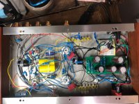
I've just built a valve preamp from a kit I got on Ebay. When I turn it on, I checked the output from the preamp and over a few seconds I see a high AC voltage of 140v which then quickly goes to zero as the amp warms up. After that it all operates fine according to tests I've done using an oscilloscope at around 2v. I am just somewhat concerned about the sudden high voltage appearing on the outputs to power amp as I switch it on. Is this normal?
I've wired all the grounds to 3 on the diagram.
Thanks very much in advance for your help
Phill
Attachments
as a rule i always turn preamp/mixer on first and amps last and do the reverse when powering down.
weird stuff happening until the supply voltage stabilizes is common as well as bizarre speaker killing noises when devices are turned off while a power amp is on is one of the reasons turn on delay circuits are so common, sounds like you need something with a 3-5 second delay and relay switch the output.
looking at the schematic and not knowing what country your in the 110v primaries if used in a120v supply country could be a problem over time.
Last edited:
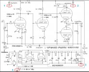
You're seeing the (ridiculously large 10uF) output coupling cap being charged though the 120K load resistor.
I'd call this normal behaviour for this design.
I'd call this normal behaviour for this design.
What you see is a bad design. change 10uF to 1uF, 120k to 12k this will prevent possible damage of the powerstage.Thanks very much in advance for your help
Except with 1uF/12k, LF starts to roll off at 130Hz... As designed, it starts to roll off at 1.3Hz...
Easier to wire a relay or switch to short the output until it's warmed up so you don't destroy the bass...
Easier to wire a relay or switch to short the output until it's warmed up so you don't destroy the bass...
Circuit diagram for relay switch
Hi,
Thanks for the help, that's great. I was wondering if you could point either to a circuit diagram for the relay switch or is there something I can wire in off the shelf?
cheers
Phill
Hi,
Thanks for the help, that's great. I was wondering if you could point either to a circuit diagram for the relay switch or is there something I can wire in off the shelf?
cheers
Phill
1uF/12k starts to rollof at 13 hz check your math ! And i assume that the users speakers don't go that farExcept with 1uF/12k, LF starts to roll off at 130Hz... As designed, it starts to roll off at 1.3Hz...
Easier to wire a relay or switch to short the output until it's warmed up so you don't destroy the bass...
google"turn on delay circuits" lots of them using 555'sHi,
Thanks for the help, that's great. I was wondering if you could point either to a circuit diagram for the relay switch or is there something I can wire in off the shelf?
cheers
Phill
Two sections of 12AX7 with a lot of gain then a cathode follower 12AU7. A bunch of loop negative feedback to lower the gain. Silly circuit for a line stage in my estimation.
Build one of Broskie's Aikido line stages. No loop feedback and no coupling capacitor between tubes. Good PSSR. Simple but effective. Even his entry level one with the built-in PS performs well as long as you build the 6DJ8 version NOT the 12AU7 version. Turn on delay isn't needed with the Aikido either.
New Aikido 12Vac PCB and part kits
Steve
1uF/12k starts to rollof at 13 hz check your math !
And i assume that the users speakers don't go that far
My math says it's -3db @ 13Hz. It stops being flat at 130Hz.
OK.
-3dB @ 13Hz = -1dB @ 26Hz, single pole.
And -1dB @ 26 Hz is quite a bit lower than my speakers can reproduce very well (they are a lot more than -1 dB there). At 26Hz, the single pole also has a 26 Degrees phase shift (equivalent to 381feet, which is quite a bit wider than the distance from my left ear to my right ear; so it may be hard to distinguish that phase shift in most music).
I am just saying, we might need to peel other layers off the Onion first, before worrying about this inner layer of the Onion.
I believe there was a reviewer or magazine that said: 'Enjoy the Music".
Not bad advice.
I suppose it depends on whether the spike will cause a problem on the amp it supplies.
Probably the easiest remedy is to add an 18v zener between output and ground.
Yes you'll get a splat if you turn on the amp before preamp, but no damage will occur.
Probably the easiest remedy is to add an 18v zener between output and ground.
Yes you'll get a splat if you turn on the amp before preamp, but no damage will occur.
See also this thread
Simple Time Delay (no more excuses for not having one)
or the bottom right part of the attachment when you really don't want to use any semiconductors at all.
Simple Time Delay (no more excuses for not having one)
or the bottom right part of the attachment when you really don't want to use any semiconductors at all.
Attachments
A 18V, 12V, or 5V zener across the output connector is going to do the following:
1. +18V, +12V, or +5V, in one direction.
2. But . . . it will have only -0.6V in the other direction (not enough signal output in the negative direction, because the zener conducts in that direction too).
3. You would have to put a diode in series with the zener to allow the negative direction signals to come through.
Output to Zener cathode, Zener anode to diode anode, diode cathode to ground.
4. Ask yourself, how much transient voltage can I put into my power amplifier before there is no damage to either the amplifier or my loudspeakers.
Last edited:
Or you could use two Zeners?
An externally hosted image should be here but it was not working when we last tested it.
A regular diode is much less leaky in the back direction than many zeners in the zener direction.
I have sometimes considered using a diode zener series pair in one direction across the signal path,
and a diode zener series pair in the other direction across the signal path for protecting tube amp inputs.
Example, A 5V zener starts conducting far before it gets to the 5V zener range.
It might start conducting at 2, 3, or 4 Volts, so using two zeners back to back in series may load the circuit down. The same can be said for other voltage ratings of zeners.
The 2 diode model (zener + diode), and for both directions the 4 diode models are more complex, but a much higher impedance.
I have just had a look at that circuit and it looks like it might be the NFB capacitor charging up through the cathode resistor of the first stage causing the voltage to rise at the output during warm up. Try moving the NFB line to the other side of the output capacitor and see if there is an improvement.
Refugee1,
If the negative feedback is causing the output spike at turn on, then it would not be more than 1.38V, the input stage cathode voltage.
The output stage cathode voltage is almost 1/2 of B+. I believe that is the voltage that the output cap has to charge up to. That is a large transient voltage.
If the negative feedback is causing the output spike at turn on, then it would not be more than 1.38V, the input stage cathode voltage.
The output stage cathode voltage is almost 1/2 of B+. I believe that is the voltage that the output cap has to charge up to. That is a large transient voltage.
Why people are looking at DC direction ?I see a high AC voltage of 140
- Home
- Amplifiers
- Tubes / Valves
- output of valve preamp showing a high voltage when turned on