The performamce of most active regulators will start to degrade above a mere 1KHz. As bwaslo alludes to, it is the impedance of the passive capacitors placed in shunt which will primarily determine the 1MHz regulator source impedance as seen by the load.
If having low source impedance supply at high frequencies is important then you will need to place high-frequency application supply bypass capacitors as close to the load as is possible.
If having low source impedance supply at high frequencies is important then you will need to place high-frequency application supply bypass capacitors as close to the load as is possible.
The performamce of most active regulators will start to degrade above a mere 1KHz.
Yes, in fact the output impedance rises from about there, and becomes inductive.
At that frequency, it probably will be the ESR of the capacitor used at its output...
Perhaps but the one thing I know for sure is that this will happen if you get the ESR of the caps on the output too low.
The picture below is actually of an LM337 and it's a bit more sensitive to oscillation than the LM317 which did not exhibit this behaviour with the same set of caps on the output. Cured with a small resistor (~ 0R2) in series with the output pin.

how much is the output impedance of the LM317 at 1Mhz? is it 0.11ohm as I read somewhere.
From the datasheet, around 7Ω:
Attachments
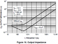
Note that figure is a measurement made at 500mA output current, at more typical small signal PSU currents (powering a handful of opamps and the like) the Zout will be considerably higher.
It might be better to say 1.1uH instead of 7R.
better way to express. Its nice to say that Im at 320Kmph than saying that im driving sports car.
Theory is a very nice thing....
until you confront it to the reality that is:
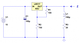
That the 317 could play the role of a perfect gyrator at such a frequency seemed very fishy, and I made a quick check.
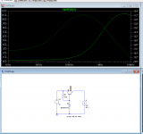
My doubts were confirmed: the impedance I measured in the conditions of the graph was |6.6Ω|, less than 10° inductive. Almost purely resistive, and if you account for the inductor isolating the load from the output, the net result is purely resistive.
Here is the test circuit (LM317 is from ST):
until you confront it to the reality that is:
That the 317 could play the role of a perfect gyrator at such a frequency seemed very fishy, and I made a quick check.
My doubts were confirmed: the impedance I measured in the conditions of the graph was |6.6Ω|, less than 10° inductive. Almost purely resistive, and if you account for the inductor isolating the load from the output, the net result is purely resistive.
Here is the test circuit (LM317 is from ST):
Attachments
OK. Surprising, but I can't argue with a careful measurement. Most feedback systems have an inductive output at higher frequencies. Maybe the 317 has internal compensation to get a resistive output instead.
I would think that whenever the Z rises with frequency, that IS inductive for the purpose of stability, output compliance and the like.
Hang a C on it and you will see a typical series resonance.
Jan
Hang a C on it and you will see a typical series resonance.
Jan
It is not Z rising with frequency which makes it inductive, but Z at a perpendicular angle.
Resonance with C is inconsistent with the resistive impedance which Elvee measured. Perhaps he could give more details of his measurement?
Resonance with C is inconsistent with the resistive impedance which Elvee measured. Perhaps he could give more details of his measurement?
1MHz is probably well beyond the unity gain frequency, and as a result, there is no more "loop" to talk about: the regulator sort of degenerates into a simple, non-servoed regulator like a zener boosted by a follower.
It is not Z rising with frequency which makes it inductive, but Z at a perpendicular angle.
Resonance with C is inconsistent with the resistive impedance which Elvee measured. Perhaps he could give more details of his measurement?
Yes that's a point. But Elvee measured it as voltage phase shift at the test generator end. I would expect no phase shift there as the generator output voltage is imposed. What should be measured is the phase shift of the current into that Zout.
Did you measure that Elvee?
Jan
A zener boosted by a follower would not show rising impedance with frequency, unless the follower was quite a slow device. Maybe it is a slow device?
A zener boosted by a follower would not show rising impedance with frequency, unless the follower was quite a slow device. Maybe it is a slow device?
Isn't the reason that emitter followers can oscillate, that their Zout becomes inductive with higher frequencies?
Jan
- Status
- Not open for further replies.
- Home
- Amplifiers
- Power Supplies
- Output impedance of the LM317 at 1Mhz?