I am new to tubes and have been reading about the topic as much as possible. I wish to understand better how to estimate the optimal output impedance of for a pp configuration when the data is not published for the tubes in use.
I think the way to do it is to use the characteristic curve for the tube and draw the ideal loadline, calculate the plate resistance at the intersection of the loadline and y axis and then find a transformer that is closer to the value x 4. Am I off? I reversed this concept for some tubes that have published data and it seems to work.
I think the way to do it is to use the characteristic curve for the tube and draw the ideal loadline, calculate the plate resistance at the intersection of the loadline and y axis and then find a transformer that is closer to the value x 4. Am I off? I reversed this concept for some tubes that have published data and it seems to work.
You must at least have the max ratings and the Ua/Ia diagram of the tube. Then use this simple tool:
www.revintage.se/PPABAMP.xls
www.revintage.se/PPABAMP.xls
revintage said:You must at least have the max ratings and the Ua/Ia diagram of the tube. Then use this simple tool:
www.revintage.se/PPABAMP.xls
Thanks, the spreadsheet still requires as input RLa-a. My initial question was how to calculate the ideal RLa-a.
Trial & Error 😉 ! Try a few until you get the right one. Just remember not to go over Pa max.
You also have to decide what "optimal" is: Max power, lowest distorsion etc.
You also have to decide what "optimal" is: Max power, lowest distorsion etc.
You shoul have the tube curves and draw the impedance lines and evaluate the power and distortion. Then you can choose the impedance and standpoint (voltage and current) for better distortion or more power.
palmas said:You shoul have the tube curves and draw the impedance lines and evaluate the power and distortion. Then you can choose the impedance and standpoint (voltage and current) for better distortion or more power.
I assume that you are talking about the curve and load line of a single tube. So, once I have this optimal impedance and standpoint, does the RLa-a for the primary of the output transformer= load line impedance X 4? (for PUSH PULL OPT)
Thanks
avincenty said:I think the way to do it is to use the characteristic curve for the tube and draw the ideal loadline, calculate the plate resistance at the intersection of the loadline and y axis and then find a transformer that is closer to the value x 4.
For tiode tubes - yup, RP * 4 should get you in the ballpark. Though note that if you know what the "ideal loadline" is, then you have the impedance; the slope of the loadline..
Chosing the best can be a matter of trial and error.
Once you've done it enough, often you can eyeball the curves and get pretty close.
The main tradeoff for triodes is that as you raise the Z, output power will drop, but distortion and output impedance will drop as well. But higher impedance transformers are hard to make with good freq response, so you there's a limit as to how high you want to go.
So, depending on the application and what the key goal is, Zl could be anywhere from nearly 1x Rp to 10x Rp.
In any case, as was mentioned, you need to observe the max power dissipation to set your operating point.
Pentodes work a little differently - the plate resistance is very high. I find the best way to pick the impedance is to take the plate curves and draw in the maximum power dissipation, and then take a ruler and start moving it around to find the best load line. You need to stay under the max power curve, though it's OK to exceed it on peaks. Find a line that gives you the biggest voltage swing. Usually that means intersecting the zero bias line near the "corner".
Pete
avincenty said:
I assume that you are talking about the curve and load line of a single tube. So, once I have this optimal impedance and standpoint, does the RLa-a for the primary of the output transformer= load line impedance X 4? (for PUSH PULL OPT)
Thanks
Yes, we've been talking single-tube loadlines.
For push-pull class-A, you want the plate-to-plate impedance to 2x the single tube load impedance (not 4). This isn't obvious... but you have to consider that you have two tubes, so the effective Rp is 1/2 of one tube...
So for class-A triode push-pull, a typical plate-to-plate impedance might be 8 x Rp (or somewhere between 6x and 10x).
Pete
Seems you guys did not check my PP calculator. It is easy to use as you use single tube loadlines and still get good approximations of what will happen IRL. There are a few faults in it that I have not corrected but is still good enough.
By fooling around with it you can find optimum working points either you want to go all Class A or want max power from a choosen tube, either triode or pentode.
By fooling around with it you can find optimum working points either you want to go all Class A or want max power from a choosen tube, either triode or pentode.
revintage said:Seems you guys did not check my PP calculator.
Who wants to use a calculator if you can do it the *hard* way?
🙂
I'll take a look at it...
Pete
Hi Pete,
Mail me if you have some ideas on how to improve/correct it without making it more complicated. Its a handy tool as a complement to ltspice. You can also check www.revintage.se/triodecalc.xls .
Mail me if you have some ideas on how to improve/correct it without making it more complicated. Its a handy tool as a complement to ltspice. You can also check www.revintage.se/triodecalc.xls .
pmillett said:
Yes, we've been talking single-tube loadlines.
For push-pull class-A, you want the plate-to-plate impedance to 2x the single tube load impedance (not 4). This isn't obvious... but you have to consider that you have two tubes, so the effective Rp is 1/2 of one tube...
So for class-A triode push-pull, a typical plate-to-plate impedance might be 8 x Rp (or somewhere between 6x and 10x).
Pete
Pete,
I agree with you, I want to learn by doing it the hard way first.
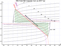
My specific question about the multiplication of the loadline impedance times the value of 4 came after reading the audio Classroom articles by Norman Crowhurst. It is the five part Designing your own amplifier. In that article he explains the relationship of the output transformer impedances versus that of the tube. Plate to Plate vs single tube. I have drawn the composite curves for the 5881 as he has in his article and also for a 7591a at Vg2=400 , bias -21. The relationship appears to be like he states it. It does not say anywhere but I think it assumes that negative feedback will be applied to improve distortion.
I have tried to attach file 5881 PP composite curve with area.png that I drew, It looks exaclty the same as in the article. I have also added a line for double the Plate Dissipation value. Interesting that the loadline barely touches this curve. The graph program that I used calculates the area below the loadline. The value of 650, is this the same as 65 watts? The composite curves of a 7591A also has a similar look, eg: the loadline is over the standard PD value, closer to the 2 x Pd. I am actually building a 7591A amp and I have noticed that a Machintosh, Fisher and HK use similar Vg2 and bias values, producing the same power ratings.
So... I wonder if this multiplier of 4 is good only for maximizing the PP power rating and for use with negative feedback.
Thanks
Alfredo
Attachments
revintage said:Seems you guys did not check my PP calculator. It is easy to use as you use single tube loadlines and still get good approximations of what will happen IRL. There are a few faults in it that I have not corrected but is still good enough.
By fooling around with it you can find optimum working points either you want to go all Class A or want max power from a choosen tube, either triode or pentode.
I tried using the spreadsheet but I don't really understand it, there are values that I can't find on the datasheets.
Do you have more detailed instructions? There are inputs for the transformer, DC impedances, Gain Pl and others that i can't seem to find or that with my limited knowledge can't estimate.
Alfredo
Hi Alfredo,
As I mentioned earlier you have to use some trial&error. A good starting point could be to use data from a few commercially available OPTs. Think you will be helped by looking at the EL84 example.
Why not start with:
Gain PI 50 * from schematic
Ua 400 A good starting point for a pair of 7591A
Iaq 50mA A good starting point for a pair of 7591A
Us from the Ua/Ia-curve you have
Rs 1k *standard value
Rl ac 7k A good starting point for a pair of 7591A
Rl dc 200 This is a good guess
Rsec 8 *
Rnfb 33 * from schematic
Rnfb 1000 * from schematic
* Does not influence on your power calculations.
avincenty said:I agree with you, I want to learn by doing it the hard way first.
Yeah, that's the best way: know why you do what you're doing, as opposed to blindly applying various formulae.
So... I wonder if this multiplier of 4 is good only for maximizing the PP power rating and for use with negative feedback.
This question gets asked so often that this really should be "stickied". Mini PP Loadline Tutorial.
That "multiplier" has nothing to do with that at all. If you calculate an Rl= 1000R per phase, that requires an impedance ratio of 1000 : 8 between the plate and the primary centertap. That impedance ratio translates into a voltage ratio of: 11.18 : 1. Since the primary needs to be voltage balanced, the total voltage ratio becomes:
2 X 11.18= 22.36 : 1 across the whole primary
This becomes an impedance ratio across the whole primary of:
22.36^2= 500 : 1 or 4000 : 8
That's where your 4 X Rl comes from. It has nothing to do with maximizing power ratios or gNFB. It applies to all PP stages, regardless of whether they use any NFB or not, nor to the type of output active device.
Miles Prower said:
Yeah, that's the best way: know why you do what you're doing, as opposed to blindly applying various formulae.
This question gets asked so often that this really should be "stickied". Mini PP Loadline Tutorial.
That "multiplier" has nothing to do with that at all. If you calculate an Rl= 1000R per phase, that requires an impedance ratio of 1000 : 8 between the plate and the primary centertap. That impedance ratio translates into a voltage ratio of: 11.18 : 1. Since the primary needs to be voltage balanced, the total voltage ratio becomes:
2 X 11.18= 22.36 : 1 across the whole primary
This becomes an impedance ratio across the whole primary of:
22.36^2= 500 : 1 or 4000 : 8
That's where your 4 X Rl comes from. It has nothing to do with maximizing power ratios or gNFB. It applies to all PP stages, regardless of whether they use any NFB or not, nor to the type of output active device.
Thank you, i think my initial assumption was correct. Find the desired loadlline impedance, multiply by 4 and find the closest OPT possible. Then I can go back with the selected impedance of the OPT and readjust the loadline for a closer estimate of output parameters.
Alfredo
revintage said:Hi Alfredo,
As I mentioned earlier you have to use some trial&error. A good starting point could be to use data from a few commercially available OPTs. Think you will be helped by looking at the EL84 example.
Why not start with:
Gain PI 50 * from schematic
Ua 400 A good starting point for a pair of 7591A
Iaq 50mA A good starting point for a pair of 7591A
Us from the Ua/Ia-curve you have
Rs 1k *standard value
Rl ac 7k A good starting point for a pair of 7591A
Rl dc 200 This is a good guess
Rsec 8 *
Rnfb 33 * from schematic
Rnfb 1000 * from schematic
* Does not influence on your power calculations.
Lars,
I did some playing around with the spreadsheet this morning and it does work. The values of the spreasheet are the same I get from doing the manual charts. I also see that you did use the multiplier of 4 to calculate the slope of the loadline from the input RLa-a cell. This was my initial question and it seems it has been confirmed.
I notice the Negative Feedback cells. How does it work? If I take the feedback from the 16ohm tap then I put 16 on the cell? You have R1 and R2. I assume this is for a voltage divider. If the design does not call for two resitors, then R1 is 1ohm like in your default value? This negative feedback currently does not affect the calculation of output power, shouldn't it?
Alfredo
Hi Alfredo,
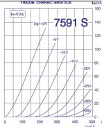
Glad you gave it a chance. A useful gadget is the possibility to see A and AB power. If you want to go all Class-A (recommended) just let the two lines intersect at Ug=0V. I also recommend you triodewire the tetrodes if you are going to use it for HiFi, see curves below. Ua425V, Iq45mA, Rl 10k, will give you just above 10W.
About the feedback cell it is for getting the sensitivity of your amp at the input of the PI. So no feedback is R1 small and R2 big. And off course it does not affect output power.
If you go triode you will not need any NFB. Tetrodes need fedback but I would not recommend more then ca 12dB.
Also noticed you are using 7591, great tubes! I am using them in my "reVintage Pro" guitar amp.
Attachments
- Status
- Not open for further replies.
- Home
- Amplifiers
- Tubes / Valves
- Output impedance for non published PP configuration