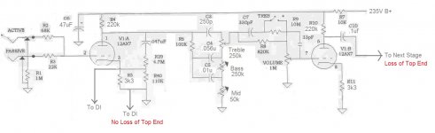
I am modifying an Alembic F2B/Fender Blackface preamp section to sound more like a blue line SVT. I am pretty much just re-biasing like the the SVT (220k anode/ 3.3k unbypassed cathode) instead of the typical Fender bias (100k anode/1.5k bypassed cathode).
I have noticed in doing so I have lost a lot of top end and have narrowed it down to the tone stack. The only thing that could have changed pre tone stack that could have effected tone would be the output impedance has gone from 39k (bypassed cathode) to 142k (unbypassed cathode).
So my question is, what effect on the tone stack does the output impedance have? None of the equations for figuring out response of the FMV tone stack take the previous stages output impedance into consideration. The tone stack also has an RC pre-emphasis circuit after it for a switchable treble boost. Could this be a possible cause of the the loss of top end (due to the impedance change)?
Attachments
Last edited:
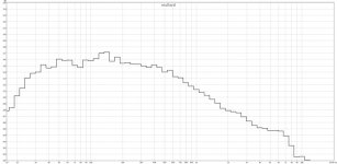
I have used the tone stack calculator and it does show a slight loss in top end, about 2db (which would be ok), but not like what I am seeing. I am seeing like a 15-20db reduction @ 10khz at a rate of about 6db per octave starting around 700-800hz.
I have looked for any potential RC circuits, and other than the tone stack, there is no cause for the roll off. There is also no roll off through the DI when taken pre eq.
I have looked for any potential RC circuits, and other than the tone stack, there is no cause for the roll off. There is also no roll off through the DI when taken pre eq.

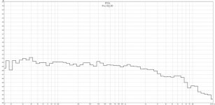
So, it wasn't the ouput impedance at all. I played with the tone stack calculator and decided that somewhere between 200k-250k would be good for R1 to try to bring some of the treble back. This got the tone stacks flat settings sounding like the pre-eq DI out, but I still had the roll off (which is apparent on the DI signal as well).
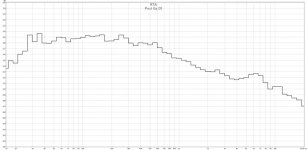
I got to looking and noticed a cap right next to the plate resistor in the first stage. I noticed that it was not on the schematic, too. After some more digging, I decided to clip it's leads. Sure enough, it was an undocumented plate bypass cap. Now I got my top end back, and then some. Now it is flat from about 29hz (by design) to 20khz with controls at noon!
I got to looking and noticed a cap right next to the plate resistor in the first stage. I noticed that it was not on the schematic, too. After some more digging, I decided to clip it's leads. Sure enough, it was an undocumented plate bypass cap. Now I got my top end back, and then some. Now it is flat from about 29hz (by design) to 20khz with controls at noon!
Hi Guys
Most bass preamp circuits have at least one of those treble shunt caps in place. Call it tradition or lethargy. Fender did it because their reference players were country thumpers using Fender instruments. The treble roll-off was useful in attaining a rounder thumpier tone and also squashed the buzz that single-coil pickups might add.
You might find it useful to add back but with a lower value simply to squash high-frequency noise and to suppress RF that might have gotten past the input grid-leak plus tube capacitance filter.
Have fun
- Status
- Not open for further replies.
- Home
- Live Sound
- Instruments and Amps
- Output Impedance Effect On Tone Stack