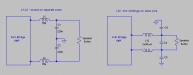
I built my first class D amp. It's a full bridge, single supply, based on LT1162 bridge driver. It sounds great, but I have some questions about output filter. Currently, my output coils are wounded on separate cores ( core EF25, 1mm air gap ), but I saw that they can be wound on same core.
1. one core is advantage ( smaller PCB, costs... ), but are there some disadvantages ?
2. how to calculate C3, C4, C5 ?
thanks.
1. one core is advantage ( smaller PCB, costs... ), but are there some disadvantages ?
2. how to calculate C3, C4, C5 ?
thanks.
Attachments
Are you sure ( C4=C5=2*C3=C2 ) ? I saw a few schematics and always is C3>C4.
What about 1st question ?
What about 1st question ?
First, when the coils are wound on the same core you only need half the windings for each coil, compared to winding on two separate cores.
Second, you don't need C4 and C5. C3 should be half that of C1.
Thirdly, remember that when calculating L1/C1, you should set Rload to half that of the seaker, in your example 4 ohm due to the ballanced mode.
Second, you don't need C4 and C5. C3 should be half that of C1.
Thirdly, remember that when calculating L1/C1, you should set Rload to half that of the seaker, in your example 4 ohm due to the ballanced mode.
Thanks for all.
But, this is full bridge amp ( not two halfbridge connected in bridge ). L1 and L2 are connected in series with speaker and calculations told me that I need 60uH ( L1=L2=30uH ). So, if they wounded on same core, L1 and L2 should be 15uH each ? Why ? ( I'm confused now )
What is purpose of C4 and C5 ? As I sad earlier, a saw them on few schematics.
Baldin said:First, when the coils are wound on the same core you only need half the windings for each coil, compared to winding on two separate cores.
But, this is full bridge amp ( not two halfbridge connected in bridge ). L1 and L2 are connected in series with speaker and calculations told me that I need 60uH ( L1=L2=30uH ). So, if they wounded on same core, L1 and L2 should be 15uH each ? Why ? ( I'm confused now )
Baldin said:Second, you don't need C4 and C5. C3 should be half that of C1.
What is purpose of C4 and C5 ? As I sad earlier, a saw them on few schematics.
If you only have a cap across the speaker (and not also a cap from each side of the speaker to ground), then any common-mode noise produced by the amp will radiate and give you big EMC problems. It is ALWAYS wise to fit C4, C5 to help filter out common-mode noise. (I've got caught by this myself before).
Believe me, there will be C-M noise at RF produced by the switching!
Believe me, there will be C-M noise at RF produced by the switching!
This is of course true. I use these my self in my bridged design. These only have to be like 10% of C3 in value. As you say Ouroboros they are ther to reduce commonmode noise, but remember that they will add to the filtering effect.
So if you have C3 = 1uf and C4=C5=100nF then the resulting "C3" will be 1,05uF (stil pretty close to 1uF though 🙂)
So if you have C3 = 1uf and C4=C5=100nF then the resulting "C3" will be 1,05uF (stil pretty close to 1uF though 🙂)
I have a very similar issue, but this forum isn't letting me start a new thread.
So I apologize, I plan on hijacking this thread if it won't let me post it.
So I apologize, I plan on hijacking this thread if it won't let me post it.
It turns out I am under moderation, and I don't know how to get out of it.
So this is my second post, hopefully a few more and I will be free.
I do apologize, I typically would add helpful and enlightening posts to someones thread, but I don't know enough to really be useful.
So this is my second post, hopefully a few more and I will be free.
I do apologize, I typically would add helpful and enlightening posts to someones thread, but I don't know enough to really be useful.
Oh, as far as C3 is concerned-- I was curious.
From what I have seen, a good reason to include C3 is because it basically doubles its effect in the filter. What other reasons are there to include it?
(By doubling, I mean connected as such, there is a virtual ground in the middle of it, and so the capacitor can be modeled as 2*C3 on both sides, going to ground, just like the first schematic. This is all basic to most of you, but its something I at least know 🙂)
- Status
- Not open for further replies.
- Home
- Amplifiers
- Class D
- Output filter