The May 21 blog on tubecad.com showed a 3 triode circuit HPA instead of the usual 4 triode version.
I had an old "Morgan Jones" HPA that wasn't really doing it for me so I changed it over to the 3 triode Aikido.
Much Better with my Senn 600s.
Book Review: Designing High-Fidelity Tube Preamps
I had an old "Morgan Jones" HPA that wasn't really doing it for me so I changed it over to the 3 triode Aikido.
Much Better with my Senn 600s.
Book Review: Designing High-Fidelity Tube Preamps
Attachments
Hello Steve,
Looks like you need someone to reply to your post.
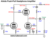
I have also built several of John’s headphone designs. Often there are magic resistor values to optimize something. This HP circuit is no exception, for example the 221R resistor is likely calculated with Chris Paul’s formula to maximize the Push Pull of the output triodes into the 300 ohm headphones.
Some interesting things to me are:
The top triode in the voltage amplifier or input section is MIA. Typically the section is a Half-mu. As it is show the plate resistor takes the place of the second triode the typical Aikido.
The noise canceling voltage divider at the bottom triode of the output tube is goofy. There is no top resistor of the typical voltage divider in the orginal post regarding Aikido Push Pull headphone amplifiers. All of the B+ noise is injected at the grid, not the typical magically calculated voltage divider. Makes me wonder if this noise injection / cancellation still needs some tweaks.
Take a look at this blog post to compare the items above.
Aikido Push-Pull
DT
Looks like you need someone to reply to your post.
I have also built several of John’s headphone designs. Often there are magic resistor values to optimize something. This HP circuit is no exception, for example the 221R resistor is likely calculated with Chris Paul’s formula to maximize the Push Pull of the output triodes into the 300 ohm headphones.
Some interesting things to me are:
The top triode in the voltage amplifier or input section is MIA. Typically the section is a Half-mu. As it is show the plate resistor takes the place of the second triode the typical Aikido.
The noise canceling voltage divider at the bottom triode of the output tube is goofy. There is no top resistor of the typical voltage divider in the orginal post regarding Aikido Push Pull headphone amplifiers. All of the B+ noise is injected at the grid, not the typical magically calculated voltage divider. Makes me wonder if this noise injection / cancellation still needs some tweaks.
Take a look at this blog post to compare the items above.
Aikido Push-Pull
DT
Attachments
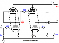
The aikido formula still holds the same even if you replace the upper half-mu triode with a resistor as shown. You only need to ensure that the plate is still at half B+ and, this will then feed the grid of the next stage with half the PS ripple. So your notion that the grid gets fed with the full PS ripple is incorrect. This is only true if the input triode is replaced with a pentode where the rp is much larger than the plate resistor. Search for Aikido Pentode on tubecad.
The aikido formula still holds the same even if you replace the upper half-mu triode with a resistor as shown. You only need to ensure that the plate is still at half B+ and, this will then feed the grid of the next stage with half the PS ripple. So your notion that the grid gets fed with the full PS ripple is incorrect. This is only true if the input triode is replaced with a pentode where the rp is much larger than the plate resistor. Search for Aikido Pentode on tubecad.
Hello that is my point.
The input stage outputs half the B+ ripple.
The output stage shown in the thumbnail I attached gets the full dose of noise injected at the grid of the lower triode, there is no upper resistor to form a divider. The original Aikido of 10 plus years ago had a voltage divider made of two 100K resistors. Then later there was the formula that reduces the top resistor of the divider to something less than 100K based the mu of the tube. For the special case of mu = 2 where the value of the top resistor is equal to 0 ohms.
DT
Member
Joined 2009
Paid Member
Hello that is my point.
Oops sorry, i have clearly misread your post.
- Status
- This old topic is closed. If you want to reopen this topic, contact a moderator using the "Report Post" button.
- Home
- Amplifiers
- Tubes / Valves
- Out with the MJ in with the Aikido