One more question: in the improved design from 00940, there was a 1200r resistor added on the B+ right after the power supply. What purpose does this serve?
I'm starting to understand tube design and how this headphone amp was really cobbled together with the wrong parts and component values...
I'm starting to understand tube design and how this headphone amp was really cobbled together with the wrong parts and component values...
I wouldn't say it's improved... we're just trying to make it work.
Forget the 1200r resistor. It was there to kind of simulate the power supply sag.
Forget the 1200r resistor. It was there to kind of simulate the power supply sag.
OK, so I pulled out the CCS board with the DN2540's and after pulling the FETs from the board, I found that both were shorting out. That's why there was only 1V difference between the Anode and the B+.
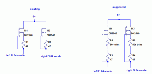
I entirely rebuilt the CCS using new DN2540's, resistors and 50r trimpots. By dialing down the current across the CCS, I am able to get a B+ of 135VDC and a plate voltage of 115V. It sounds wonderful. Far less distortion and the background is dead silent.
I then tried to reroute the circuits on the board (remember, this is a PC board for the other amp like in the schematic, that has OT's) to put the output coupling cap off of the source of the DN2540 instead of at the plate. What I got was some pretty bad motorboating, so I put everything back to the way it was laid out.
I also ordered the parts to restore the feedback loop with a 12k resistor and a 47pf ceramic cap in parallel. The spots for those are on the PC board as well. I just need to move around some of the internals.
Thanks for all of the help. I now have a properly working little headphone amp with far less distortion and perfectly balanced channels.

Good work. With shorted fets, it's indeed not surprising that you had a serious problem.
Too bad for the motorboating. It might be a consequence of the subpar PS and/or some oscillation of the mosfets due to layout. But if the amp sounds good as it is, no need to loose sleep over it.
- Status
- Not open for further replies.