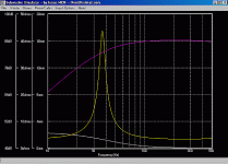
I ran your parameters through Subwoofer Simulator. Below is the graph I got.
All of these are for an input of 2.83 Volts. So that is 2 watts. We can scale up in a moment.
The purple line is your amplitude response.
The yellow line is your impedance response.
The white line on the bottom is your excursion-for 2 watts input.
All of these are for an input of 2.83 Volts. So that is 2 watts. We can scale up in a moment.
The purple line is your amplitude response.
The yellow line is your impedance response.
The white line on the bottom is your excursion-for 2 watts input.
Attachments
The 6 dB boost at 25 or 30 means nothing excursion-wise. When driven to it's limit, this subwoofer puts out 272 watts, boost or no boost.
Now to do some scaling. Your subwoofer amp probably has a filter that cuts under 20 Hz. So the worst case scenario is the excursion at 20 Hz. After that, your amp should cut the amplitude, therefore the excursion as well.
As you can see, at 20 Hz you are slightly less than halfway betwen 0 and 4 mm. Let's just say that you are .45 of the way to 4 mm. That's 1.8 mm. For 2.83 volts input.
However, 272 watts into 4 ohms requires 33 volts, not 2.83 volts. I won't bore you with the math, but that comes to 21 dB over.
Here is the way it works. In a sealed box, if you want to raise the aplitude 6 dB, you multiply the excursion by 2.
If you want to raise the amplitude 9 dB, you multiply the excursion by 3.
If you want to raise the amplitude 12 dB, you multiply the excursion by 4.
We need to raise the amplitued 21 dB to find what our excursion will be at 20 Hz. It is presently 1.8 mm. at 2.83 volts.
So if we raise the amplitude 12 dB, that is 4 times the excursion. That leaves another 9 dB we must raise it.
So we multiply the excursion by 3 again. So that is a total 4 times multiplied by 3 times. that equals 12 times.
1.8 times 12 equals 21 mm. About 1.8 times your linear excursion.
On the other hand, if your subsonic filter is 3 dB down at 20, then your excursion would be 25% less, or 15.75 mm, certainly within your woofer's capability.
At 25 Hz, your woofer appears to be about 1.6 mm at 2 watts. That is 19 mm.
Generally, you can count on the mechanical limit being 18 mm at least. Probably more. I would also point out that in the nonlinear range-over 12mm-you get power compression, which means that the woofer really does not move all the way to the point where it should. That is why they call it the nonlinear range. So that will save you some excursion.
You are just about borderline to your speaker's excursion, but I think you will be okay.
kelticwizard said:The 6 dB boost at 25 or 30 means nothing excursion-wise. When driven to it's limit, this subwoofer puts out 272 watts, boost or no boost.
However, 272 watts into 4 ohms requires 33 volts, not 2.83 volts. I won't bore you with the math, but that comes to 21 dB over.
Here is the way it works. In a sealed box, if you want to raise the aplitude 6 dB, you multiply the excursion by 2.
If you want to raise the amplitude 9 dB, you multiply the excursion by 3.
If you want to raise the amplitude 12 dB, you multiply the excursion by 4.
We need to raise the amplitued 21 dB to find what our excursion will be at 20 Hz. It is presently 1.8 mm. at 2.83 volts.
So if we raise the amplitude 12 dB, that is 4 times the excursion. That leaves another 9 dB we must raise it.
So we multiply the excursion by 3 again. So that is a total 4 times multiplied by 3 times. that equals 12 times.
1.8 times 12 equals 21 mm. About 1.8 times your linear excursion.
On the other hand, if your subsonic filter is 3 dB down at 20, then your excursion would be 25% less, or 15.75 mm, certainly within your woofer's capability.
At 25 Hz, your woofer appears to be about 1.6 mm at 2 watts. That is 19 mm.
Is that not consuming 272 W rather than putting out?
And what is the math behind the scaling. If 6 dBs mean multiplying excursion by2, 9dB means 3 times, 12 dB means 4 times then why does the match suddenly change and 21 dB not equal 7 times the excursion rather than 12? Does that make sense? Surely either it is twice the excursion for every 3 dBs (giving 2*2*2*2*2*2*2 = 128 times the excursion) OR it is linear so that it is 7 times the excursion for 21 dBs but not both ways at the same time? Quite different results though.
/UrSv
I got the internet at my folks' house
The plate amp's response is 3dB down at about 20 Hz
Thanks for your help. I can't wait to build this killer music sub!
(0.5 Qtc = "Transient-Perfect")
The amount of HT I try to do will be minimal. By the time I can have a dedicated home theater system, I will be in a place that can accomodate an SVS subwoofer.
Okay. Just to add a couple of things about nonlinearities.
As I stated before, once it leaves it's linear range, your speaker will not go as far as the signal tells it to.
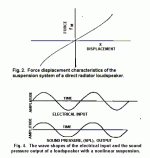
The following charts are from the late HF Olson, an engineering pioneer in audio, radio broadcasting and quite a few other things. Former head of the The Audio Engineering Society.
These charts were taken from his April 1962 article in the Journal Of The Audio Engineering Society. It is also reprinted in their Loudspeaker Anthology, Part 1. The title is "Analysis Of The Effects Of Nonlinear Elements Upon The Performance Of A Back-Enclosed, Direct Radiator Louspeaker Mechanism".
See how, in both charts, at some point the response flattens out? That is what happens when you leave the linear area of loudspeaker travel. Obviously, your Blueprint has a lot longer linear travel than anything around in 1962, but once it leaves the linear area, the effect is the same, whether in 1962 or 40 years later.
I honestly cannot tell you point blank that everything is safe, but most indicators seem to indicate that you will be alright. To which I would also add that when speaking to the tech support of Pyle speakers some years ago, the tech said that "everyone" runs subwoofers out of the linear area. If you have any more doubts, perhaps the best thing is to call or Email Blueprint, just to get their "take" on the situation.
If you do so, let us know what they say.
By the way, I would say that is extraordinary performance from a 1 cubic foot box!!
Off to Thanksgiving dinner! 🙂
Attachments
UrSv:
Interesting math questions. I base my figures on the idea that if you have to increase something proportionally, and then increase it again proportionally, you use multiplication, not addition. Maybe I got that wrong.
The following link brings you to a chart I copied from Richard Small in his article from the Journal Of The Audio Engineering Society. It is how much air must be moved to get a given SPL. His chart was in cubic entimeters. I posted the chart both in cubic centimeters and cubic inches.
http://www.diyaudio.com/forums/showthread.php?threadid=5668&highlight=SPL+displacement+chart
If you look at either chart, you see that an increase of 10 times the volume of air moved yields an increase of 20 dB.
272 watts raises the decibels 21.3 over an input of 2 watts. The formula is 20 Log (V1/V2). 33 volts yields 272 watts at 4 ohms. 2.83 volts yields 2 watts at 4 ohms.
So just by eyeballing it, we know that BAM needs an increase of just over 10 times his cone excursion to go up 21.3 dB.
My scaling calculations yield 12 times. If I am off, it isn't by too much.
My original contention that he should have no trouble was based on the idea that his 10" driver would have 56 sq inches of cone area. The Blueprint must have a big surround, or they figure it different. Anyway, they list his cone area as only 47.8 square inches. Also, the volume per SPL formula Subwoofer Simulator uses might not be exactly the same as Small's.
I remember reading an ariticle in the Journal Of the Audio Engineering Society where they tested the realistic limits of bass reproduction given real-world loudspeakers and what can be expected of them. This was back in the 80's. Their calculatons were somewhat off-not drastically-from Small's chart. I think Small's chart required more volume than the article's formula. At any rate, I decided to go wth Subwoofer Simulator's readings.
Regardless, it was a good question. I just made some assumptions that I should have thought through better. As it turns out, it looks like I was right, but it is good to consider these things.
If anyone on this forum knows about volume and SPL output, jump right in. I'm not an engineer-maybe there is more to this. 🙂 🙂
Catch everyone later. Off to dinner. And football.
Kelticwizard
Hey kelticwizard,
How do you use that program?
I input my woofer T/S parameters, but can't get any graphs to display?
What am I doing wrong?
Thanks.
Hey kelticwizard,
How do you use that program?
I input my woofer T/S parameters, but can't get any graphs to display?
What am I doing wrong?
Thanks.
Even though you are almost there, I will start from the beginning for anyone reading this.
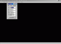
1. Click "New"
2. Click "Woofer" and input info-you can "X" the box when you are done, the information will stay there. Everything is in Metric. Not the author's fault-he's Australian. 😉 Equivalents at the end of this post.
3. Click "Boxes" and then click "Sealed", "Vented", whatever.
4. Input info for desired box-you do not have to click "Maximally Flat", that is just an option. Again , you can "X" the dialog box and the info is retained.
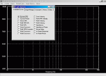
5. Click "Graph Options" and go through the whole list. IMPORTANT: Click "Available Curves" so the program knows what you are looking for. THEN click "Boxes", and check the sort of box you want-in this case, sealed. A line should appear on the graph immediately after you check the box.
6. You can go through "Graph Ranges", "Colors", etc. if you want, but that is all you need. You might want to peruse the "Colors" box so you know which line is representing what. You can change the colors for any curve-nifty.
NOTE: Amplitudes are given for 2.83 Volts @ 1 Meter only.
If you have an 8 ohm speaker, that is one watt.
If you have a 4 ohm speaker, that is 2 watts. Subtract 3 dB for the 1 watt output.
If you have a 2 ohm speaker, 2.83 vots is 4 watts. Subtract 6 dB for the 1 watt output.
Metric Equivalents
1 cubic foot = 28.3 liters
1 inch = 25 mm or 2.5 cm
1 square meter = 1550 square inches. So take the number of square inches in your cone area and divide by 1550. A 10" woofer likely has a cone area of 56 square inches, so the cubic meters = (56/1550) = .0361 square meters.
For other Metric programs, you should know that 1 square inch = 6.25 square centimeters.
Also, when calculating Volume of displacement, (Vd), one cubic inch equals 15.6 cubic centimeters.
One of the great things about this program is that it automatically calculates the SPL from the Thiele-Small parameters. Some manufacturers are a little optimistic on that number. This gives a more accurate picture-just remember the importance of ohms when considering that figure.
Hey, guess what. Subwoofer Simulator is even better] than I thought. I just found out that you can change the input power so that you can see the response with 100 watts, 200 watts, or more!
Click "Graph Options" and then "Constants". Erase 2.83V and put in whatever voltage your amp is putting out at your highest wattage.
Be sure to adjust the "Graph Ranges" so the curves don't go over the limits of the graph.
Don't know the voltage for your watt output?
V = number of volts
R = rated impedance of your speaker
Watts =V2 /R
thanks for the info, but...
Hmmmm....
I still don't get anything on the chart, I see the scale, but no grafted lines.
I'm not sure what to put in for Ql and Qa...
Hmmmm....
I still don't get anything on the chart, I see the scale, but no grafted lines.
I'm not sure what to put in for Ql and Qa...
THE EASIEST WAY to use that equation is to just try different voltages, square them and divide by the ohms of your speaker.
If you have a 4 ohm speaker, 20 volts = 20 squared,or 400, divided by 4-which equals 50 Watts.
25 volts will yield 25 squared divided by 4. Which is 156.25 Watts.
30 volts will yield 30 squared divided by 4 ohms, which is 225 Watts. And so forth.
Once you find the voltage of your amps top wattage, you can enter the voltage into Subwofer Simulator and get the curves for the speaker when driven at top wattage.
I hope I have not insulted anyone by going through the math. It's just that once you are out of school a few years, this stuff becomes forgotten rather quickly, and I just thought I would review it for hobbyists who are not in a tech field.
Re: thanks for the info, but...
Don't put anything. I don't. That has to do with box quality, and since we are building the best box we can, what difference does it make?
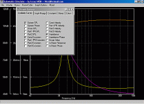
Make sure at least one of the boxes in the picture below is checked.
Let me know how you make out.
WolfmanX said:I'm not sure what to put in for Ql and Qa...
Don't put anything. I don't. That has to do with box quality, and since we are building the best box we can, what difference does it make?
Make sure at least one of the boxes in the picture below is checked.
Let me know how you make out.
Attachments
i must be extremely dense...
I can't seem to get anything on the chart, don't know what I'm doing wrong.
I'm trying to look at the Titanic MKII and the Adire Audio DPL12 in sealed boxes with cone excursion, SPL, etc.
Thanks for the help, but I must be helpless...
I can't seem to get anything on the chart, don't know what I'm doing wrong.
I'm trying to look at the Titanic MKII and the Adire Audio DPL12 in sealed boxes with cone excursion, SPL, etc.
Thanks for the help, but I must be helpless...
LOL, I don't think you are dense. Your other posts here strongly indicate that you are not dense.
I just realized I left out an important step in my previous instructions.
Let's just get something on the graph first, even if it is not your preferred driver. Then you can work from there.
1. Click File-New Project.
2. Click "Woofer". Numbers will appear. Don't change anything, you can do that later once you get started. Just look at the numbers, then "X" out of the dialog box.
Attachments
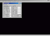
Once you have "X"ed out of "Woofer", click on "Boxes". When you click "Sealed", the foollowing dialog box will appear. Remember, this is just a dry run to show how things work.
Don't change anything, don't click "Maximally Flat", just look at the numbers and "X" out of it.
Don't change anything, don't click "Maximally Flat", just look at the numbers and "X" out of it.
Attachments
Now this is the important part I left out before, LOL. Sorry. Will contact moderator to change that previous post.
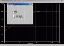
Second from right on the dialog box, there is a selection named 'Boxes". Click it.
Then check the "Sealed box" selection when it appears.
Immediately, you should see a curve appear in the background.
Second from right on the dialog box, there is a selection named 'Boxes". Click it.
Then check the "Sealed box" selection when it appears.
Immediately, you should see a curve appear in the background.
Attachments
Then just "X" out of the "Graph Options" dialog box, and you have your curve.
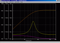
Once you have the hang of this program, you can go back to the "Graph Options" selection, click "Available Curves", and check as many curves as you want. In addition to leaving "System SPL" checked, I checked the "Cone Excursion" and "Impedance" boxes, and this is what I got:
Once you have the hang of this program, you can go back to the "Graph Options" selection, click "Available Curves", and check as many curves as you want. In addition to leaving "System SPL" checked, I checked the "Cone Excursion" and "Impedance" boxes, and this is what I got:
Attachments
- Status
- Not open for further replies.
- Home
- Loudspeakers
- Multi-Way
- Other bass boost post
