Next 4 batteries in parallel supplying power = 12V under load.
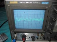
Interestingly, I can see the modulation on the PS at low vol.
I expected the batteries (low impedance PS?) to sound better than the SMPS but I find it more polite as if lacking power!
Interestingly, I can see the modulation on the PS at low vol.
I expected the batteries (low impedance PS?) to sound better than the SMPS but I find it more polite as if lacking power!
Attachments
actually the PS rail being variable is not a form of volume control. it's an efficiency feature. the PS will only generate the amount of voltage it needs for the power level expected (determined by the volume control setting). unlike a class H amp (which has a power supply that is regulated by the audio envelope) this PS "ballparks" the supply voltage.
Sorry Unclejed, in these XR range of Panasonic amps, this is a feature - the vol control is by means of adjusting the PS voltage to the output stage - from -70 down to-44dB the volume is adjusted digitally, from -43 to -32dB volume is controlled by voltage adjustment 10V to 41V in steps, after that voltage fixed & vol controlled digitally again
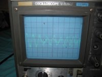
What do you think of the scope pics?
What do you think of the scope pics?
the flash makes it hard to see...... i've seen scope hoods that are used for cameras. it's usually a plastic truncated pyramid shaped box that attaches to the bezel. that's what the ridge on the top of the bezel is for. a scope hood (you could make one out of cardboard) would make for some really nice scope pictures and block out extraneous light. it also comes in handy when you want to view a very dim trace (usually at very high sweep speeds)
i have a few more Panasonic receivers to repair this next week. i'll take a closer look at the service manual to see what they say about the PS voltage and volume control.
i have a few more Panasonic receivers to repair this next week. i'll take a closer look at the service manual to see what they say about the PS voltage and volume control.
This really is impossible to comment on at a distance, would have to see to last detail what you are doing and where everything is connected. What was ripple voltage with all working normally. Are you testing under load with continuos signal (sine wave) or music and into what, speaker or dummy load. I am not trying to put you off, it's the only way to really learn, I remember some of the things I used to try, class D headphone amp from TTL logic was one, I would take nothing on trust, just had to find out for myself.
I can't help but feel Unclejed is correct about the volume issue. I too would have said the rail tracks the expected output required. When we are talking about digital audio, levels are precisely set and known, e.g. it is impossible for a 16 bit C.D. player with a max output of 2vrms to generate anything over this, an analogue source, lets say vinyl, this has no max upper limit theoretically. So the amp "knows" what the max output can be and limits the supply accordingly as to where you have set the volume. In a class D amplifier the volume or output is altered by varying the output mark/space ratio, the audio waveform is "recovered" by means of a low pass filter. What frequency is the output stage operating at, same for the PSU ?
Regards Karl
jkeny said:Next 4 batteries in parallel supplying power = 12V under load.
Interestingly, I can see the modulation on the PS at low vol.
I expected the batteries (low impedance PS?) to sound better than the SMPS but I find it more polite as if lacking power!
when you use battery , you must decouple with big good caps ( like for any traditionnal psu ) to lower the internal impedance
Hi rha61,
I did use 10,000uF cap in parallel with battery - still seeing PS modulation with music.
Hi Karl
I'm sure about the volume control being done by altering the PS as I stated above - it's an advertised feature of the SA-XR range of Panasonic receivers.
Ah, I was hoping for more feedback as to what to do next - I'm taking the readings with music playing into speakers (load) and not playing (no load).
Where do I go from here?
How do I see the ripple voltage? - this is what I'm looking to measure, so as to try improving this & also learn how to use a osc!
With the very greatest respect this is not the way to learn how to use a 'scope. Talk about jumping in at the deep end 🙂 . You need to understand what the 'scope actually does and how to interpret the results. This will end in tears  . You need to understand what you are seeing. Measure the calibration voltage of your 'scope, do you see what the display is telling you. Measure a battery, on the scope, do you understand what it is showing you. If you are intent on measuring the ripple on the main supply it's negative lead of scope to negative terminal of C717 and probe tip to positive terminal C717. Scope on A/C coupling at say 5v per div to begi with, timebase reasonably slow to start, say 5 milliseconds per division. Read the peak/peak ripple and expand the timebase to show the ripple waveform.
Regards Karl
. You need to understand what you are seeing. Measure the calibration voltage of your 'scope, do you see what the display is telling you. Measure a battery, on the scope, do you understand what it is showing you. If you are intent on measuring the ripple on the main supply it's negative lead of scope to negative terminal of C717 and probe tip to positive terminal C717. Scope on A/C coupling at say 5v per div to begi with, timebase reasonably slow to start, say 5 milliseconds per division. Read the peak/peak ripple and expand the timebase to show the ripple waveform.Regards Karl
As to this "volume thing" have a think about this, a bit of lateral thinking if you like. If the volume really was set by the value of the supply rails, then any interference, ripple voltage, fluctuation under load, all of which happen, this would by definition be reproduced as changes in volume. This would cause AM (amplitude modulation) distortion and the performance figures would be spectacularly bad.
Ok, Karl,
That's the sort of info/admonishment I need - I will go away now & study a bit - will report back when I have anything useful to say!
Edit: Your second post came in after I posted - about the volume control, tell this to Panasonic because it definitely is part of the amp - look at the schematic again - the whole shaded area is where volcont signal is fed back & varies the VDD output!
And this is why I'm trying to measure the ripple/quality on/of the PS!!!!!!
And btw, the performance figures for this amp are not bad at all, for an open loop no-feedback amp, however they do it - just in case your thinking why bother with this piece of **** anyway!
The amp's volume really is controlled by PS voltage. It's open loop class D, aka an open loop buck regulator Vout=D*Vcc.
Thank you Tim_x,
It carries so much more authority when you use the correct terminology!
Have you any views on the quality of this PS? - areas for improvement?
It carries so much more authority when you use the correct terminology!
Have you any views on the quality of this PS? - areas for improvement?
ok, i'll agree if you're saying they're operating it open loop that the PS voltage can be used as a volume control method, but it's a crude way of doing it. the output waveform audio is a percentage of the rail voltages. but any amp operated open loop is going to have a higher THD than one operated closed loop. for this amp to have any decent performance the transfer characteristic has to be extremely linear to begin with. which means the triangle wave used in the comparator and the modulator have to both be extremely accurate. not an easy thing to do.
Ok, this is going off topic now - I didn't want a discussion on the pros/cons of open/close loop or volume control systems- my whole point in starting this thread was to find out how to use an oscilloscope with the intent of measuring this PS as I was aware of the sensitivity of this type of scheme and I wanted to test out various caps etc!
It is overcomplicated and somewhat crude, but that doesn't change the fact that that is how it works.
Most power DAC style amplifiers are openloop. With zero PSRR the amplifiers performance is limited by the PS. In terms of noise, distortion and output impedance, such an amplifier can never be better than the power supply. That's why the power supplies are so complicated and necessarily high performance.
It's become a fairly common topology, with Panosonic and TI doing it among others.
- Status
- Not open for further replies.
- Home
- General Interest
- Everything Else
- oscilloscope in audio tutorial