Is there a recommended tutorial for Oscilloscope use in audio for a noob?
Couldn't find anything with a search!
Couldn't find anything with a search!
Quite a vast subject really, is it just the basics you want or more advanced measurement techniques. There used to be a few books on this subject years ago. Have you tried searching for any out of curiosity ?
Regards Karl
Regards Karl
Actually, I did a search on interweb & found some basic guides - is there any special considerations for audio use?
Not really 🙂 . You can't beat experience. For audio use a 20Mhz or better dual trace scope is fine. Use with proper probes e.g. switchable 1/10 1/1 . It's the details when measuring to watch, the scope measures peak voltages not R.M.S. values e.g. 680volts peak/peak is mains voltage. DONT TRY AND MEASURE THIS. Please remember that the scope is earthed (or should be) and this means that the earth wire of the probe is also earthed. If you are working on say an amplifier that is also earthed, I am sure you will see what would happen if you connected the probe ground lead to anything other than earth in the amplifier. If there is anything specific you want to know please do ask.
Regards Karl
Regards Karl
Thanks Karl,
That's the sort of info I was looking for - stuff you won't find in a textbook but hints/tips that come from experience.
If I want to measure the ripple on a SMPS power supply how do I do it?
That's the sort of info I was looking for - stuff you won't find in a textbook but hints/tips that come from experience.
If I want to measure the ripple on a SMPS power supply how do I do it?
You would ask that would'nt you 😉 . The primary side of the PSU is out of bounds, to work on this you need a mains isolation transformer and all earths disconnected, with NO earthed equipment within reach. All test equipment, soldering irons etc run of this "floating supply". This is normal practice in repair workshops, not very practical at home. So you are limited to working on the output or secondary side. To measure the ripple on a S.M.P.S. you connect the earth lead of scope to the common earth point on the secondary side. There may be several different rails to measure but they will, 99% of time have a common earth or ground. Then just measure ripple with scope on AC coupling so you can see ripple superimposed on DC voltage. Again experience is the key. An unstabilised supply might have a 1 volt or so pk/pk . The noise or ripple output of a regulator eg 7805 should be as low as say 5 millivolts. The correct point on the common ground makes a huge difference to result. Our 7805 reg would require you to connect directly to centre pin and output pins in order to get accurate result, move the ground lead a few centimeters along the PCB track and the reading could rise a hundredfold due to the resistance of the track. If you have a specific circuit you want to work on post the diagram and will tell you where and what to measure and what to expect. Remember to increase the timebase speed on scope as ripple on SMPS is high frequency, not 50hz. Have fun and stay safe.
Regards Karl
Regards Karl
actually, with a dual trace scope there is a way to make measurements on the line side. put the scope in "ADD" mode and set channel 2 to "INVERT". channel 2 goes to the line side common and channel 1 to whatever you are trying to measure. of course you have to null the scope (connect both probes to line common and adjust for no deflection) before you make a measurement. you are reading the differnce between the two probes (hence the name "DIFFERENTIAL" mode). this cancels out the line voltage sine waves on which your line side DC voltages "float". this is much safer than working "hot chassis" with the scope. make sure you use a scope with at least 1kv max input if you're working with 240v line voltages.
Thanks Karl,
Sure might as well start with the difficult stuff first - many thanks for your directions & help - I will stick with just the secondary side of the SMPS - it's actually a SMPS of a Panasonic Digital amplifier SA-XR57 with a variable voltage which determines the volume.
Because it's an non feedback digital equibit technology the PSRR is low or non-existent & PS quality is more of an issue than with other amps - hence my interest in testing this (& possibly improving it)
Thanks unclejed,
But as a oscilloscope noob I think I'll stay safe & stick with secondary testing for the moment!
Unclejed, I have never ever heard of this being done, it sounds very workable in theory though. Are you able to get meaningful readings, checking the drive to a chopper transistor for example with all the noise and hash flying around. You are correct in saying a 1000v input rating would be required, most scopes seem to be in the 400 to 600 vdc range, even most divider probes are only 400vdc or so rated. It is non the less a very interesting proposal with the right kit.
Very interesting indeed, Karl
Very interesting indeed, Karl
I think less electronics than this put man on the moon  .
.
There are 3 separate SMPS in there, it's such a complex circuit you need the full sheet in front of you to see whats going on. T701 /IC701 main PSU and don't be fooled by the grounds shown, everything around IC701 is directly connected to the mains, those grounds are NOT the same as the grounds to the left of chopper transformer T701 , it looks like T721/IC721 is for a separate standby supply (same warning). Your IC703 appears to control via IC702 and opto PC701 the "main " ht supply for the amp. You can measure the ripple directly across C717 and C718 but there are multiple supplies all over the place. The optoisolator's are there to couple the feedback signal from secondary to primary side of supply, in other words from the safe side to the live mains side. Please be careful working on this + I think most engineers would run a mile on seeing this circuit. And thats without T731/Q731, this is a SMPS fed off a SMPS, again the full circuit in one piece is needed to appreciate how it all works together. It's a technical masterpiece at the end of the day, but I can't help feeling it's way over the top for audio, it's main advantage of course is efficiency, switching regulators and class D outputs. Just try taking it down the corner shop and saying "well there's not a lot wrong with it, just a loose wire or something" 😀 😀 😀 and BE CAREFUL.
Regards Karl
.There are 3 separate SMPS in there, it's such a complex circuit you need the full sheet in front of you to see whats going on. T701 /IC701 main PSU and don't be fooled by the grounds shown, everything around IC701 is directly connected to the mains, those grounds are NOT the same as the grounds to the left of chopper transformer T701 , it looks like T721/IC721 is for a separate standby supply (same warning). Your IC703 appears to control via IC702 and opto PC701 the "main " ht supply for the amp. You can measure the ripple directly across C717 and C718 but there are multiple supplies all over the place. The optoisolator's are there to couple the feedback signal from secondary to primary side of supply, in other words from the safe side to the live mains side. Please be careful working on this + I think most engineers would run a mile on seeing this circuit. And thats without T731/Q731, this is a SMPS fed off a SMPS, again the full circuit in one piece is needed to appreciate how it all works together. It's a technical masterpiece at the end of the day, but I can't help feeling it's way over the top for audio, it's main advantage of course is efficiency, switching regulators and class D outputs. Just try taking it down the corner shop and saying "well there's not a lot wrong with it, just a loose wire or something" 😀 😀 😀 and BE CAREFUL.
Regards Karl
Thanks Karl,
Agreed, it's a complicated multi-voltage PS but the main voltage (and the one I'm interested in) is the red line that comes from T701 and goes to connector as VDD - this is adjusted by volcont to output different voltages as a means of volume control (the shaded circle on the schematic) - quiet sophisticated I think.
My main concern is to measure & minimise the ripple on this VDD
Thanks, I will be careful!
It will be interesting to see what readings you get. The ripple will vary according to the current drawn from this rail. Are you testing under load ? To get an accurate reading you must ground scope probe directly on negative end of C717 and C718. The quality of these caps is absolutely crucial. I am sure they will be highly specified parts with a very low E.S.R. and low self inductance.
Regards Karl
Regards Karl
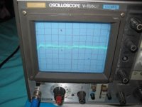
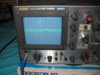
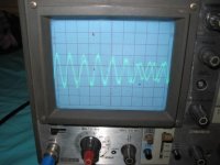
Here's some pics - not very good I'm afraid - showing clearest trace I could get on the scope. They are for:
- amp with no load and 10,00uF cap between PS board & Output Board
- amp with no load and no cap connected
Don't know if you can see all the squiggles? but there are more on the second photo. What is the significance? I presume a clean, low impedance PS would be a straight line? Camera ran out of battery before I could connect up 12V 7ah battery to power outputs stage!
I haven't included the pics but under load there were more squiggles as the vol increased & they modulated with the music!
Attachments
- Status
- Not open for further replies.
- Home
- General Interest
- Everything Else
- oscilloscope in audio tutorial