I have this OPT made by AE-Europe, it is a dual bobbin on a C-core. It is 3200:8R. Each bobbin has a primary and a secondary winding. The primaries go in series, while the secondaries go in parallel.
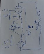
My current speakers is about 40 ohms (8 woofers in a line array), so it is possible to connect the secondaries in series, to obtain a 3k2:32R OPT. The winding ratio on each bobbin is therefore 10:1. That 10% of the primary looks like a nice value for cathode feedback, so I setup the schematic below, using 25DQ6Bs. For testing I have a 50R dummy load.
And, it oscillates. I also inverted the connection at the cathodes, thinking I might be applying positive feedback, but it still oscillates. I measured the oscillation at about 17kHz, couple volts at the cathode, lots at the plates.
I connected the cathodes to ground, and then the thing works, all signals clean with the expected high gain and high distortion…
Am I doing something wrong? Suggestions?
Thank you all! Erik
Attachments
Just a few obversations . . .
1. You do not have any grid stoppers. Put a non-inductive 1k Ohm resistor between the 1uf cap and the grid of each tube.
For sure, your circuit without that looks to me approximately like a cross between a Butler Oscillator and a Hartley Oscillator, in push pull.
And, is the oscillation 17kHz, or is it bursts of RF at a 17kHz rate?
2. Did you check the connection of all the windings with a signal generator and a scope or a DMM to verify the phase of all the windings?
Do not rely on manufacturers phase markings.
Example, with the amp powered down, and all capacitors discharged:
Apply 1V 1kHz across 1 primary winding, then it should read 2V from plate to plate (2 primaries in series).
Then apply 1V 1kHz across 1 secondary winding, then it should read 2V from cathode to cathode (2 secondaries in series).
3. A real 50 Ohm Non Inductive load resistor is a good thing.
A 50 Ohm wirewound resistor is not a good thing.
A series connection of woofers has a very large amount of voice coil inductance.
It is not a 40 Ohm load, because it is a very high impedance at 17kHz (high inductance at 17kHz).
Last edited:

Output transformer design and construction requires a lot of experience. Not many manufacturers have that, certainly not the newbies in the market.
You have to realise that the transformer inter winding capacitance and the inductance result in a resonant circuit. You have to try to figure out where it is. Just being a C-core with dual bobbins does not neccessarily means it will work for CFB.
1uF from g1 to ground? Seems excessive. You'll need a stopper to g1, to the screen (both as close as possible to the tube pins), for good measure some ferrite beads there as well and a 50 Ohm 2 Watt carbon resistor with 5 turns winding from one end to the other end wound on that resistor body ibetween the plate and the OPT (and as close as possible to the tube socket. You may also want to consider using cathode feedback from each cathode to the OPT rather than fixed bias.
You can also try a 5K - 20K resistor in series with a 5nF cap between the plates to take the sharp Q out of the output transformer.
Not to foget that woofers can have a sharp resonance peak.
If the windings are not exactly the same between sides (primary and secondary) then you'll wind up with an oscillator.
PS I have no experience with PP CFB, only SE. I do wonder how much interaction there is between the cathodes through the speakers and if that is causing you the grief. Perhaps get a proper McIntosh OPT?
Last edited:
Erik,
If I understand correctly you have a normal OPT and use the secondary winding for speaker AND cfb.
For cfb you need a transformer with separate cfb windings.
Ite
Schematic + LTspice model:
https://www.diyaudio.com/community/threads/ltspice-hierarchical-ultralinear-opt.379431/post-6890338
If I understand correctly you have a normal OPT and use the secondary winding for speaker AND cfb.
For cfb you need a transformer with separate cfb windings.
Ite
Schematic + LTspice model:
https://www.diyaudio.com/community/threads/ltspice-hierarchical-ultralinear-opt.379431/post-6890338
If you are willing to accept the very slight DC offset on the speaker, you do not need separate windings. Original poster has a non-normal setup, but a common 0-4-8-16 output is in a number of amps grounded at 4 ohms and feed cathodes from 0 and 16 for cathode feedback.Erik,
If I understand correctly you have a normal OPT and use the secondary winding for speaker AND cfb.
For cfb you need a transformer with separate cfb windings.
Ite
1. If the two secondary winding's DCR are equal, and if the output tube currents are equal . . .
Then there is no DC offset to the speaker that is connected across the two series secondaries.
2. A separate cfb winding is not needed, as long as the 10:1 winding ratio you have gives as much negative feedback as you want to use.
3. There are lots of amplifiers, both diy and commercial that use the output secondary windings to provide negative feedback to the cathodes.
The most often used method is to ground the 4 Ohm tap, and then connect the cathodes to the 0 Ohm tap (common), and the 16 Ohm tap.
However, this means that the output has to be tested by putting the scope probe ground on the 4 Ohm tap, and then measure from that tap to either the 0 tap, 8 tap, or 16 tap.
4. If you mistakenly connect your scope probe to the 0 Ohm tap, and with the 4 Ohm tap grounded to use cathode negative feedback, you will short out the signal (and perhaps make it oscillate).
+1 on post upper
i'm doing it regulary, PP with CFB. i have no any problem at all, but i'm using 0-4-8-16 ohms technique where 4 ohms is GND, 0 ohms goes to first cathode, ¸16 ohms to the second. if is oscillating i'm changing g1 and g2 input wires. also one must be sure about that there is no positive feedback applied, it is easy to measure with the oscilloscope, output on the speaker with NFB and without. with NFB signal must be smaller of course.
i'm usually connecting it over the oscilloscope and mark properly..i never even consider that manufacturer mark some wires "for me" . also last 10 years i'm winding my own transformers so it is easy to plan CFB 🙂
here we have 40 ohms speakers. why 40? try to put all in paralel-series to have some normal impedance.
then what kind of schematic is this? there is no any connection for the bias, and grid leak resistors, why we need to use telepathy methods on public forums? 🙂 maybe grid leaks are too big which is not helping.. also i never saw PP amp connected without stoppers (ok some guitar but this is wrong approach by default) so 1kohm need to be there..
bepone,
Yes. I agree.
erikdeBest,
40 Ohms / 8 drivers = 5 Ohms per driver.
Connect 2 drivers in parallel, 2 drivers in parallel, 2 drivers in parallel, and 2 drivers in parallel.
Each pair is 2.5 Ohms.
Then connect all 4 pairs in series, 2.5 Ohms x 4 = 10 Ohms.
That will increase the damping factor of the speakers (8 drivers in series has very poor damping, because 8 x 'series DCR' is a problem, no matter how low the amplifier output impedance is).
Of course with 10 Ohms on that transformer,
Either The secondaries need to be wired in-phase in parallel (so the idea of using negative feedback to the cathodes is no longer possible),
Or a different transformer is needed.
Rewiring the speakers in 4 series parallel groups, and re-wiring the secondaries in parallel will probably kill the oscillations.
No cathode negative feedback, the damping factor will be low, but try it . . .
Listen to the working amplifier for a week before thinking of doing any further mods or improvements.
Then with no cathode feedback, it is time to try 'screen negative feedback' (Tie the screen through a 100 Ohm resistor to the plate.
Triode wired mode, less power, but with more finesse, and higher damping factor.
Happy missing oscillations!
Happy Listening!
Just my opinions.
Last edited:
Many thanks for all of your replies!
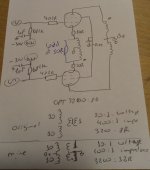
With respect to the transformer: it is indeed not made specifically for cathode feedback, just that theoretically it should work and the 10% of the primary is about ideal. AE Europe is relatively well known manufacturer, and the fact that it is a dual bobbin design suggests both sides could/should be quite well matched. After I detected the oscillation I wired the 10R at the cathodes straigtht to ground, and then the amplifier behaved like expected, so the windings are correctly identified.
I unfortunately did not take a picture of the oscillation, but it looked as a classs AB at 17kHz, I say class AB because measuring the voltage at the cathode showed that the of the sine was clean, but the bottom was flat (because of the valve being in cut off).
With respect to the speakers. They are line arrays with 8x4R woofers. Wiring is with a plug and socket so I can use all in series (for max impedance), or 2 strings of 4 in series (for "normal" 8R impedances). I do that because I am also playing with some OTLs, which like the higher impedance. https://www.tubecad.com/2010/12/blog0195.htm Indeed, there is the RDC of all drivers in series... wiring them all in series just allows some extra flexibility, like using cathode feedback with an OPT that would not allow it with the conventional parallel connection of the secondaries.
I am currently mostly interested in output stages, so I have big adjustable PS for B+, B++ and bias voltages, and different drivers stages with SE and balanced outputs delivering some 10s of volts of undistorted sines, or music. So putting an output stage together is relatively straightforwarded, and in this case it just misbehaved. After the failed CFB attempt I tried some plate to grid feedback, and that worked nicely - next try will be based on the V69 from Telefunken (http://www.hifi-forum.de/bild/telefunken-v69_646189.html) MOst of my ramblings work, just the ones that do not end up as discussion points here 🙂
The schematic I showed before was after detecting the oscillation and taking out some parts that I thought could be contributing to it. I am attaching the circuit, including the grid stoppers and the gridleaks. There are indeed no resistors on G2, maybe I should try those. The output valve I am using, the 25DQ6B, is not a high transconductance, so if it really needs 1k? The load of 50R are two 100R wirewound resistors (these white ceramic ones) in parallel. Not ideal, I know, but should not cause such misbehaviour (and they do not when not using the CFB). As I mentioned earlier, I also tried reversing the connections to the cathode, thinking I was maybe applying positive feedback, but interestingly the outcome was the same oscillation.
Attachments
Pentode operation makes the tube's plate impedance, rp, very high.
The only thing in your circuit diagram that reduces the plate impedance, rp, is the cathode negative feedback.
Some output transformers do not behave well with pentode operation and global negative feedback, and even may not behave well with pentode operation and local feedback around the output transformers.
Apparently and empirically in your case, you have discovered that.
Using Schade negative feedback from the output tube plate to the driver stage plate often works very well because it does not include the phase shift of the output transformer's primary to secondary (gain and phase relation).
Using modified Schade negative feedback from the output tube plate to the driver stage cathode often works very well because it does not include the phase shift of the output transformer's primary to secondary (gain and phase relation).
I use Non-Inductive load resistors when testing my amplifier designs. I test harmonic and intermodulation distortion, frequency response, hum, gain, damping factor, output power, clipping, rise time, fall time, etc.
Only after that do I connect the amplifier to a loudspeaker load.
I use a test CD's single-sample burst to check the amplifier's frequency response when connected to the loud speaker.
(loudspeaker = a reactive load).
Then I listen to music.
Just my opinions, and experience.
Last edited:
Hi 6A3,
it was indeed all the discussions about the local feedback around the output tubes that triggered my interest in the CFB as a "simple" alternative. I have not given up yet on it, and EL506 had some suggestions as well, so there is still work to do.
You may remember a previous thread where I asked about a transconductance amplifier, and you came with some suggestions, including the R in series with the drivers. I tested that and found it does not hurt, so I can live with the slightly higher output impedance because the OPT is not in the local feedback loop.
But while I test new circuits I make sure there is always something working to play the tunes 🙂
Hi ErikdeBest,
I remember our current source amplifier discussions.
Funny, I have 5 tube amplifier chassis, all are mono-blocks, no two are exactly alike. 4 are working (but one or more often gets modified to try a different idea). I have one next to the computer; one in the bedroom; one downstairs next to my workbench; and one spare to move around or to try out a modification.
At some point I will make two the same to do stereo (I used to have two of those chassis with two channels for stereo). I only have one working ear, and lots of recordings have about 90% of the music in both the Left channel, and in the Right channel. A scope XY display shows me how different the L and R channels are, or how alike they are for a given recording.
The fifth one is completely unwired, except for the B+. I plan to make that one a 2 stage balanced amplifier to work with a balanced output CD player that I have.
hello Erik, it is ok your experimenting. this is the way to learn and play with tube circuits!
i see that you have high-ish Rg resistors of 680k , i know it is written 1Mohm max, but pls reduce it to 330k.
also 1uF is bias cap? increase this to 100uF bias circuit must be stable.
to be able to connect properly CNFB and to be sure that polarity is ok, and remove all the other factors from the oscillation problem, i would do next:
1) connect the circuit in triode mode (g2-anode 100 ohms 2W). cathodes to ground, verify that is working . if ok, pass to 2)
2) connect cathode circuits like in your schematic, verify there is no oscillation, if there is oscillation then try all 4 connections
2a) input 1 -> g1a, input 2-> g1b, Cathode 1-> to secondary 1 , Cathode2 to sec 2
2b) input 1 -> g1a, input2-> g1b, Cathode 1-> to secondary 2, Cathode 2 to sec 1
2c) input 2 -> g1a, input 1-> g1b, Cathode 1-> to secondary 1, C2 to S2
2d) input 2 -> g1a, input 1-> g1b, Cathode 1-> to secondary 2, C2 to S1
when you loose the oscillation, meens that you have been establish proper combination of connections and you have really negative feedback, not positive like now
2e) if you dont loose oscillation in all 4 connections, then you have layout problem, remove all and start from the 0, it is very bad layout, where are your capacitors supplying the nodes? their grounds are also critical where to connect
if in triode if oscillations are lost, then,
3) connect again to pentode, remove 100R from g2's and connect again to grid supply and see if oscillations are gone
if oscillations here in pentode mode are returned, goto 2e), layout problem 90%
Last edited:
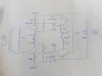
Meanwhile I tested the Telefunken V-69 "concept" with these OPTs (wired for 8R secondaries), with feedback from the plate to the source of the drivers. 25DQ6Bs at output, FQPF3N80C as driver. At an output of 2W there was 0.12% THD, but only 2nd, and at 30W there was 0.56% THD (waterfall, with 4th and up >70dB below). I played with the source resistor (now at 400R) to get a gain of about 19x (~26dB), which is what I need. Distortion over the whole bandwith was very good also (measured with STEPS, from Arta).
So, at least I know the OPTs work and the phases are well. So, one of the next steps is indeed to follow bepone's recommendations and retest the cathode feedback!
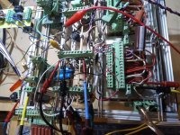
I am attaching the schematic and the mounting, It is a rats nest, but I understand it 🙂
So, at least I know the OPTs work and the phases are well. So, one of the next steps is indeed to follow bepone's recommendations and retest the cathode feedback!
I am attaching the schematic and the mounting, It is a rats nest, but I understand it 🙂
Attachments
bepone,
I agree, although a floating secondary that is not used for negative feedback, there is a very remote chance that the amp may oscillate (a floating secondary lowers the capacitance of the primary to ground, versus grounding the secondary).
But you gave me a very good reminder; prevent possible shocks.
A floating secondary is a shock hazard.
Although primary to secondary shorts are rare, it only takes one shock to kill;
Kill under the wrong conditions (under the right conditions, if you look at it that way).
With global negative feedback, Or Without global negative feedback, ground one terminal of the output transformer secondary.
Grounding the 0 terminal is the Common thing to do. Pun intended, but it also is true.
It makes testing easier when you connect a scope probe, etc. or connect other auxiliary equipment.
I had a brand new output transformer. It had a short from the primary to the laminations and end bells.
Although it was not a primary to secondary short, it does show that bad quality happens.
Watch for this, before you build a breadboard amplifier. Ouch!
Be sure to scrape the paint off the end bells where the mounting screws contact, or use some method to ground the lams and end bells to the chassis.
Safety First!
Prevent the "Surviving Spouse Syndrome".
ErikdeBest,
Yes!
I much prefer the negative feedback from the output plates to the driver cathodes (versus Schade plate to plate negative feedback).
Happy Listening!
Yes!
I much prefer the negative feedback from the output plates to the driver cathodes (versus Schade plate to plate negative feedback).
Happy Listening!
That jumble of wires reminds me of 'How to Make an Oscillator'!Meanwhile I tested the Telefunken V-69 "concept" with these OPTs (wired for 8R secondaries), with feedback from the plate to the source of the drivers. 25DQ6Bs at output, FQPF3N80C as driver. At an output of 2W there was 0.12% THD, but only 2nd, and at 30W there was 0.56% THD (waterfall, with 4th and up >70dB below). I played with the source resistor (now at 400R) to get a gain of about 19x (~26dB), which is what I need. Distortion over the whole bandwith was very good also (measured with STEPS, from Arta).
So, at least I know the OPTs work and the phases are well. So, one of the next steps is indeed to follow bepone's recommendations and retest the cathode feedback!
I am attaching the schematic and the mounting, It is a rats nest, but I understand it 🙂
When running speakers in series each speaker becomes the others source impedance.
6A3, i have experience with PP EL95 small tubes no any NFB , which were oscilating on high volume, on quiet no any problem, and i needed 6 months to ground secondary to stop the oscillations. after all kind of standard anti osc. methods, it was needed only one piece of black wire at the end 🙂 😀bepone,
I agree, although a floating secondary that is not used for negative feedback, there is a very remote chance that the amp may oscillate (a floating secondary lowers the capacitance of the primary to ground, versus grounding the secondary).
But you gave me a very good reminder; prevent possible shocks.
Many thanks for all the replies. With 8R I do indeed ground one side of the secondary winding.
On my way to work I was thinking about it (unfortunately I have more time to think than to fiddle on the actual circuit), and realized something. As I said, it is a dual bobbin transformer. On each bobbin there is an (interleaved) portion of the primary (anode) and secondary (speaker/cathode), the two primaries go in series, the two secondaries, usually, in parallel. I wired the whole thing so that the "phase dot" of the primary match with the "phase dot" at the speaker (to keep track of phase throughout the building). This does, however, imply that in the cathode feedback connection the windings on a tube are inverted: one tube has the primary of bobbin 1 and the secondary of bobbin 2. Maybe in theory this should not be a problem, but well, that is the theory. Also, at higher frequencies the core does (almost) nothing, so I think it is best to keep the coupling of anode and cathode winding as tight as possible. So I will be rewiring (with short wires 🙂 ) the whole thing to check this. What do you think?
Also, on the later V-69 based schematic I replaced the enhancement FETs with depletion (DN2540) and now I can just ground the center tap of the input TX secondary, no more need for bias. Using basically the same resistor values I increased the gain (22 vs 19) and distorion (0.15% vs 0.12%) a bit, so may have to increase the source resistors a little bit. All in all quite happy and this will certainly be made into a more definitive build.
best regards,
Erik
Attachments

- Home
- Amplifiers
- Tubes / Valves
- Oscillation with cathode feedback