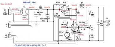
Something went wrong with the 82k measurements. V3 pin 7 is nowhere near 150V, or was this a typo when reporting results?
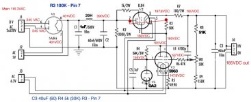
The 100K one looks best - V3 RH now drawing 2mA (voltage across R3 divided by R3 value). You could try 120K too, but probably not much difference. You want R3 current to be around 1-2mA across the whole output voltage range, so V3 is reasonably balanced.
The 100K one looks best - V3 RH now drawing 2mA (voltage across R3 divided by R3 value). You could try 120K too, but probably not much difference. You want R3 current to be around 1-2mA across the whole output voltage range, so V3 is reasonably balanced.
A typo. Should be 147v - so its pretty balanced in that area too. So should I wrap it up with 100K? If so I need to get a higher wattage resistor. I'll be out today so I need confirmation so I can buy at least a 1 watt. When I measured across the 68K it was .5W and I only have .5W resistors in 100K - less in the lower resistance. No need to try R3 back to cathode and the other lower resistances, right? Just want to be sure before I leave in case I need to pick up other resistors. I haven't listened to it with these changes yet. Just wanted to get the results off.
Last edited:
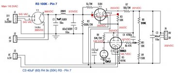
I just did some more measurement with the 100K. Looks like the output dropped to 185V which means I no longer need to adjust R8 - a great outcome. However, when I adjusted the PSU output to 202V needed for me to get 200V on the signal tube plates the voltages changed across the PSU. I guess as expected although I didn't expect it. Here are three more readings to review which also include the corrected 82K. I listened and the hum is down from before but I believe higher than it used to be. If you decide 100K is still the answer I can pick up a couple 50K and center tap to see if that helps.
Attachments
Last edited:
I would stick with 100k in total. However it is marginal on power, as you say. This will be less of a problem if you split it but may still be worth using 1W components. Try 18K 0.5W, 82K 1W with the centre decoupled. 82K at the V3 end, not the C2 end.
You could also try decoupling the EL84 screen grid. Some of the hum will be getting in here.
You could also try decoupling the EL84 screen grid. Some of the hum will be getting in here.
Arggghhh! I just got back and picked up every value but 18K!! 
I did pick up 1W 100K though. And 1W 51K (no 50K).
How should I decouple the grid? Split the resistor value in half and junction to ground? Looks like the 1K 2W and goes to grid. Otherwise the grid goes to pin 6 of the 5963.
Ramping it up to the target output voltage still looks good though, right?
I did pick up 1W 100K though. And 1W 51K (no 50K).
How should I decouple the grid? Split the resistor value in half and junction to ground? Looks like the 1K 2W and goes to grid. Otherwise the grid goes to pin 6 of the 5963.
Ramping it up to the target output voltage still looks good though, right?
51K is an E24 preferred value. 47K (E12 value) would do just as well and might have been cheaper. A 50K resistor would be very expensive, and not generally stocked. As I said, 20% error is plenty close enough for most circuits! So the 18K, as it only makes a small part of the total, can really be anything between 10K and 27K. Use whatever you have. (BTW if you want to learn about component values, Google E24 E12)
The EL84 screen grid (pin 9?) just needs a capacitor to ground i.e. at the end of the 1K resistor. Anything over 10uF should do. If it makes no difference to the hum then omit it. We don't split the resistor on this one as we are not putting a signal here, unlike the control grid.
The EL84 screen grid (pin 9?) just needs a capacitor to ground i.e. at the end of the 1K resistor. Anything over 10uF should do. If it makes no difference to the hum then omit it. We don't split the resistor on this one as we are not putting a signal here, unlike the control grid.
More great information. Thanks! When you say at the end of the 1K you don't mean at the tube pin but at the other side of the 1K? Or at the tube pin?
I'll play around and then wrap it up hopefully so I can have a musical weekend.
I'll play around and then wrap it up hopefully so I can have a musical weekend.
At the tube pin, as I said. It is the EL84 screen grid you are decoupling. The other end of the 1K already has a capacitor to ground - C2!
My weekend starts about 7pm on Friday (3 hours from now in UK) so it would be nice to get this all wrapped up.
My weekend starts about 7pm on Friday (3 hours from now in UK) so it would be nice to get this all wrapped up.
Duh. In making sure everything was clear I didn't focus on the obvious C2. Have a great weekend. I have plenty to go on from here out. Thanks again for all your incredible help!
I also want to thank everyone who responded in this thread. I truly appreciate it. If I frustrated some of you I apologize. I had it in my mind there was a simpler solution which DF96 happened on. I'm sure your solutions would've worked I just didn't want to muck about in that part of the supply. None of that takes away from the kind help offered another to audio builder.
I also want to thank everyone who responded in this thread. I truly appreciate it. If I frustrated some of you I apologize. I had it in my mind there was a simpler solution which DF96 happened on. I'm sure your solutions would've worked I just didn't want to muck about in that part of the supply. None of that takes away from the kind help offered another to audio builder.
I'm glad you got it working at last.
I think I now understand what was making the original circuit so unstable. It had too much gain, and the gain was very dependent on the applied load. The EL84 was acting as a current amplifier, because the 50K went to its cathode. Current gain maybe 500 times? This was multiplied by the transconductance of V3, and the loss (approx half) of the voltage setting divider resistors. So the whole thing, before feedback, was acting as a high gain transconductance amplifier. This means that the open loop voltage gain was determined by the applied load. If no load, then just the voltage setting divider PLUS the final capacitor. This gave 90 degrees phase shift. Any further phase shift then meant that the feedback became positive.
This circuit might work OK in its original setting with a high constant load on it, but it was not suitable for any other purpose as it is inherently unstable. Note that taking an output from a cathode doesn't necessarily mean that you have a cathode follower with low output impedance - you also have to make the input a voltage source referenced to ground and not the cathode. This problem could arise with a bootstrapped cathode follower.
The new circuit has a voltage amplifier followed by a cathode follower. Lower gain, and inherently lower output impedance. So more stable, and more widely applicable.
Hi, phrarod,
I would suggest to built new regulated PSU around tube-era schematics, which are proven for over 40 years, e.g. stabilizers from Russian L1-3 or L3-3 testers.
I do not know origin of your schematic, if its relatively new it may be designed by an engineer with low level experience/knowledge in tube electronics with any side effect possible.
Pentodes like EL84 are prone to oscillation.
Many thanks again. Supposedly this circuit was based on a Jadis board. But who knows. For more feedback - the cap on the grid had no effect.
A pair of resistors (68K/32K) with the junction to ground started to burn the 1W 68K resistor. So I just put in a 1W 100k. In the past when I referenced to ground from the center of two resistors like that I used equal values. Don't know if that made any difference. I just was able to put it in my high efficiency system and its warming up now. Hope to have an uneventful night of music.
LinuksGuru -- I'm going to a true dual mono choke loaded 5AR4 supply so this experiment is over. I just need it to work for a couple months while I await parts.
Its been playing for probably 16 hours over the last couple days without issue (hope I didn't jinx anything by saying that).
The 100K 1W R3 runs about 30-40º F hotter than all the other resistors on the psu. ~170-180ºF. I'll try and find a 2 Watt somewhere.
Its very well balanced now that I can run it at voltage/current. The only knock I would give it is the other version when stable had more slam. This has good dynamics and accuracy. That's the only thing missing. Hopefully the new simple choke loaded non-regulated PSU's will resolve that.
I just wanted to add - I've never seen the VR tube light up this brightly. I had to always look real closely to see if it was even lit. Now I could read by it 😀
Well almost.
Well almost.
Hopefully final update. Been working without a hiccup for closing in a week and I would a good 50+ hours.
- Status
- Not open for further replies.
- Home
- Amplifiers
- Tubes / Valves
- Oscillating PSU above certain voltage