Can anyone send me a copy of the profile as a .sldprt file? I can change the thickness on my own unless it's hardcoded somehow, in which case I would like the thickness to be 0.5 mm.
Working directly with the equations (to create the profile) hasn't yielded much success for me.
Working directly with the equations (to create the profile) hasn't yielded much success for me.
Which part of the curve does the waveguide use?
How much elongation of the ellipse is required to create a good, or "best", waveguide shape?
Do we truncate some part of the curve to match the included angle of the throat? Which part?
When these or this curve is selected, does any part of the waveguide actually become a cone/conic?
I've read a lot of Gedlee, but could not find any of that info.
Last edited:
I also have trouble with the equation feature. What I do is use johnk's spreadsheet, copy the image, then trace it in sw with a spline.
Trace it so that it is visually matching? How many spline points do you use and how close can you get, e.g. some thou off, or more?I also have trouble with the equation feature. What I do is use johnk's spreadsheet, copy the image, then trace it in sw with a spline.
All of it, from what I know. The mouth size is dictated by the frequency to which you want to maintain pattern control. The profile is thereafter curved to reduce diffraction.Which part of the curve does the waveguide use?
There are some spreadsheets floating around that handle this sort of thing. I believe there is some reiteration required, depending on how the math is being handled, but the throat and profile will change somewhat based on the driver's exit angle.Do we truncate some part of the curve to match the included angle of the throat? Which part?
No idea.When these or this curve is selected, does any part of the waveguide actually become a cone/conic?
OK, got it. I used John K's Excel spreadsheet to get the values of the constants as follows:
Let:
tan(A)^2 = C
B = "B" from the spreadsheet
then use explicit equation:
y(x) = (B+(x*C)^2)^0.5
where
x1 = "X Throat"
x2 = your desired waveguide depth (this is a function of how low you want your pattern control and/or desired mouth size)
Fairly simply now that I think about it. The sketched profile is accurate to how many significant digits of the constants you input into the equation.
Which part of the curve does the waveguide use?
How much elongation of the ellipse is required to create a good, or "best", waveguide shape?
Do we truncate some part of the curve to match the included angle of the throat? Which part?
When these or this curve is selected, does any part of the waveguide actually become a cone/conic?
I've read a lot of Gedlee, but could not find any of that info.
1- all of it except a small portion at the throat and then there is a termination at the mouth which should be flared.
2 - I have no idea what this is asking.
3 - You have to match the initial angle of the waveguide to the exit angle of the compression driver. Mathematically this is not so easy, but I have seen it done somewhere. Its just the simultaneous solution of two constraining equations. (Not that that is trivial!)
4 - The OS asymptotically approaches a conic section but is never actually purely conic.
5 - This is all in my book - Geddes, not GedLee (which you can now download for free), but the book assumes a high level of math comprehension. I can't make it "simple" because it is not.
OK, got it. I used John K's Excel spreadsheet to get the values of the constants as follows:
Let:
tan(A)^2 = C
B = "B" from the spreadsheet
then use explicit equation:
y(x) = (B+(x*C)^2)^0.5
where
x1 = "X Throat"
x2 = your desired waveguide depth (this is a function of how low you want your pattern control and/or desired mouth size)
Fairly simply now that I think about it. The sketched profile is accurate to how many significant digits of the constants you input into the equation.
So you got this to work? I'll give it a shot.
When using a spline I was using 4 points. I'd draw the throat angle and exit angle to determine the start and end points, scale the excel image onto my drawing, then trace the curve.
Thanks for your answers, but I am still left scratching my head.
The oblate spheroid is an ellipse.
An ellipse starts at some point and goes around the curve to return to the start point.
That closed curve cannot be a waveguide.
so the question was:
I'll leave the other questions until after some Member helps me see this.
The oblate spheroid is an ellipse.
An ellipse starts at some point and goes around the curve to return to the start point.
That closed curve cannot be a waveguide.
so the question was:
Which part of the curve does the waveguide use?
I'll leave the other questions until after some Member helps me see this.
Oblate spheroidal coordinates - Wikipedia, the free encyclopedia
the hyperboloid sheets of revolution are the "orthogonal" level curves in the OS coordinate system
the hyperboloid sheets of revolution are the "orthogonal" level curves in the OS coordinate system
An OS refers to the oblate spheroidal coordinate system. In one plane the circumferential lines are ellipses, but we use the radial lines as the waveguide boundary and they are not ellipses. Actually the surfaces of a constant radius are not actually ellipsoids, only their cross sections are.
Just Google Elliptical coordinates and you will see the contours. A waveguide any radial line rotated about a normal to the origin - which in this coordinate system is a short line.
PS> Bingo JCX - the blue surface is an OS waveguide. The equation is the intersection of the yellow plane and he blue surface. The wavefronts follow the red surfaces.
Last edited:
The equation for an OS waveguide with arbitrary initial angle:
R(x) = sqrt(R0^2 + 2*R0*tan(F)*x + (tan(A)*x)^2)
x .. distance from the throat along the WG axis
R(x) .. radius of the WG at x
R0 .. radius of the WG at the throat
A .. coverage angle
F .. initial angle
You can derive this easily in cartesian coordinate system.
- Oh, BTW, OS waveguide is a superb device! 🙂
I've already tried sizes from 10" to 18" and it's still getting better. If I may advise, save yourself time and money and go with the largest waveguide/woofer you can right form the start.
Last edited:
If I may advise, save yourself time and money and go with the largest waveguide/woofer you can right form the start.
'BIB' [bigger is better] was my conclusion also way back when I experimented with conical WGs, same as I'd already learned from experiments with TLs and vented [mass loaded] variants.
FWIW, I wound up with basically the same size as a tar filled Lansing/Altec 1803 multi-cell's outer casing, mouth dimensions, though tapered for a 1" exit CD rather than a 1.4" exit. XO was 500 Hz/2nd order, so the dual 15" woofers were ultimately mounted horizontally and up against the bass-bin's top plate to keep driver spacing acceptable for the listening distance.
From this I learned about polar responses of multiple drivers as up till then I had them in the traditional vertical plane that I was never really pleased with.
GM
GM, does it really go well to use a 1" exit compressiondriver as low as 500Hz? I would have thought it would stress it to much, but maybe in a home audio application it is ok?
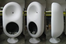
This is some nice work: hifi.slovanet.sk :: Zobrazi� tému - Dvoupásmo 18" + 18" OSWG
It's 18" OSWG with 18" woofer. You don't need to speak Czech to peek at the photos down the thread. The driver is P.AUDIO PA-D45 and will be crossed over around 700Hz. The raw WG measurement is in the first post.
It's 18" OSWG with 18" woofer. You don't need to speak Czech to peek at the photos down the thread. The driver is P.AUDIO PA-D45 and will be crossed over around 700Hz. The raw WG measurement is in the first post.
Attachments
Last edited:
inside there is a 1.7" to 2" driver moving the air.GM, does it really go well to use a 1" exit compressiondriver as low as 500Hz? I would have thought it would stress it to much, but maybe in a home audio application it is ok?
When the efficiency is up around 30%, only 70% of the input power gets converted to heat. That is a big reduction in heating of the Voice coil.
GM
Is all this based on measurements or just listening? I'd love to see measurements.
So would I, but unfortunately the cost of such measuring equipment back in '69-'75 when I did the majority of my experimenting/DIY speakers for others was well beyond this then family man's means. I did do some crude polar plots using a calibrated SLM borrowed from work along with some from Altec to guide me to confirm what my ears were telling me, but saw no reason to save them.
As for deciding I much preferred the larger horns/lower XO, this was strictly from mine and some musician's listening plus my then wife's keen HF hearing to dial in the HF bypass caps.
What interested me most though was the wife preferred the 500 Hz, making me wonder if it's more gender related since the female's BW is shifted a bit higher. After that revelation I used females to 'voice' speakers for others when applicable and the men never complained.
GM
GM, does it really go well to use a 1" exit compressiondriver as low as 500Hz? I would have thought it would stress it to much, but maybe in a home audio application it is ok?
It depends on how large the horn is to ensure it doesn't excurse too much. The WGs I made were 90 x 40, 44" wide by 17" high x 27.5" deep + throat adapter + depth of driver's throat initial conic expansion. The trade-off of course is that this much acoustical mass, HF response suffers. Not many 'free lunches' in speaker design.
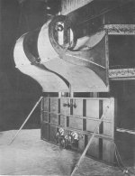
Bell Labs/W.E.'s original large cinema horn used a 1" exit CD coupled to a ~15 ft long path-length expo horn terminating at a ~64 ft^2 mouth to get a usable 50-5 kHz BW.
Of course it beamed like a laser up high, so they added super tweeter horns to its massive OB 'sub' as a quick fix, but it didn't really help enough plus added so much time/phase offset 'echo' that the race was on to come up with a better design.
Still, this horn by itself 'set the bar' for human voice reproduction and the only system I've auditioned to match it is DSL's SH-50 Synergy horn. All I felt it needed was a smoother, more mellow HF.
GM
Attachments
- Status
- Not open for further replies.
- Home
- Loudspeakers
- Multi-Way
- OS waveguide profile