Hi,
in my PCM53 project with SM5803 & DENON chip for data conversion I have a problem.
The SM5803 datasheet from the web is incomplete, page 130 is missing.
SM5803 unfortunately has a seriel input register with 13 flags to set output data word length etc.
Now I have no idea how to input the data to set those flags, this information is on the missing page.
Any other OS filter I can use ?
I need
20 bit output
output COB
left and right data parallel out
4 x OS
Or can I go directly zero OS from CS8412 to the DENON chips ?
There I need bitclock, wordclock, data left, data right.
I can't find any other parallel-output, 4X digital filters.
You could use something like a DF1706 in 4X mode, followed by a CPLD doing serial->parallel conversion, as discussed in the "elegant way to feed..." thread.
You could use something like a DF1706 in 4X mode, followed by a CPLD doing serial->parallel conversion, as discussed in the "elegant way to feed..." thread.
rfbrw said:What is the point of sending 20 bit data to a 16bit dac ?
The DENON chip only accepts 20 bit, otherwise there is noise only.
It works with the SM5813 but it is 8 x OS and in the datasheet the PCM53 is only specified to work on 4 x OS.
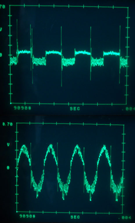
Also again I have the positive and negative spikes ( very close to each other ) on every zero crossing of the 1kHz signal..
No deglitching or filtering yet, just measured on the output pin of the PCM53.
gmarsh said:I can't find any other parallel-output, 4X digital filters.
You could use something like a DF1706 in 4X mode, followed by a CPLD doing serial->parallel conversion, as discussed in the "elegant way to feed..." thread.
Sorry, not parallel bits, just one pin for left and another for right channel data.
What I do not need is alternating l/r data output.
There must be a big bug.
Pictures show -60dB and -80dB 1 kHz signal.
-80 dB already looks like a square 🙁
Wrong data format ?
I had exactly the same problem or even worse when fitting the PCM53 in a JVC player whitch originally has PCM54 DAC.
Edit:
If you look closer, you can see the square from -80dB also in the -60dB signal.

Why not just build a jig for the purpose of testing? Unless you are testing a dac in its intended design, the odds are you will need some added logic.
Bernhard said:
<snip>
when fitting the PCM53 in a JVC player whitch originally has PCM54 DAC.
<snip>
Why?
According to my data sheet, for 4X parallel mode, you set the OMD flag H. and the 8X output (pin 5) H also. Is that any help?
Jocko
Jocko
rfbrw said:
Why?
The old story: I don`t have a 2 x PCM 53 player to test how one chip per channel performs.
rfbrw said:Why not just build a jig for the purpose of testing? Unless you are testing a dac in its intended design, the odds are you will need some added logic.
I don`t understand. What is a jig ? Where will I need additional logic ? I`m looking for a way to implement two pieces of PCM53 in a DAC. Not so easy...
Jocko Homo said:According to my data sheet, for 4X parallel mode, you set the OMD flag H. and the 8X output (pin 5) H also. Is that any help?
I know.
But how please can I access the flags ?
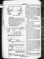
This page is missing in my datasheet. (p.130)
Still my main problem is how what you see in the picture can happen.
A -80dB sine is converted to a noisy square.
Maybe 8 x OS with DENON chip and SM5813 is good.
Otherwise if there is no filter that fits, I must use the 74HC logic instead of the DENON chip.
Or zero OS direct from CS8412.
But that will not solve the square problem.

A -80dB sine is converted to a noisy square.
Maybe 8 x OS with DENON chip and SM5813 is good.
Otherwise if there is no filter that fits, I must use the 74HC logic instead of the DENON chip.
Or zero OS direct from CS8412.
But that will not solve the square problem.

In this case it would be a pcb with a ZIF socket or number of sockets with jumpers or switches that allows one to interconnect various dacs etc. .Bernhard said:
I don`t understand. What is a jig ?
In this specific case, to load the registers that set the output wordlength of the SM5803 or to generate the needed signals if you choose to bypass the filter or connect the CS8412 to the directly PCM53.
Where will I need additional logic ?
Are you building from scratch or trying to modify an existing device?
I`m looking for a way to implement two pieces of PCM53 in a DAC.
It is if you know how.
Not so easy...
rfbrw said:
In this case it would be a pcb with a ZIF socket or number of sockets with jumpers or switches that allows one to interconnect various dacs etc. .
I have such thing with CS8412, SM5813, SAA7220.
rfbrw said:
In this specific case, to load the registers that set the output wordlength of the SM5803.
Yes, and this is my second problem, where is page 130 of the datasheet ?
rfbrw said:
Are you building from scratch or trying to modify an existing device?
I build a new DAC.
rfbrw said:
It is if you know how.
Always like this.
rfbrw said:So you want to build a new dac using a single PCM53 shared between both channels?
No. A new DAC using a pair of PCM53 or PCM52 or DAC71 with zero or 4 x or 8x OS.
One PCM53 in this very TEAC player already measures better than a TDA1541 or a pair of PCM54 / 56 / 58 / 63.
And to my ears also sounds better.
Bernhard said:
A new DAC using a pair of PCM53 or PCM52 or DAC71 with zero or 4 x or 8x OS.
Then you will need some glue logic whatever you do.
I don't know what page 130 is. I have a data book that has a page 130. Nothing on it about setting registers. I do not see much of anything useful in the copy that I have. It mentions the order that the control bits are loaded in, but it means nothing to me. Is that what you need to know?
I know zero about programming. You will have to give me more specific requests for me to find what you need in my copy.
And, no..........it will not scan properly...........too small and not the best printing to begin with.
Jocko
I know zero about programming. You will have to give me more specific requests for me to find what you need in my copy.
And, no..........it will not scan properly...........too small and not the best printing to begin with.
Jocko
- Status
- Not open for further replies.
- Home
- Source & Line
- Digital Source
- OS filter Problem
