Hi All,
Does anyone have a schematic diagram for the Orion XTR2500.4 amp?
It is a four channel Bipolar Transistor output section using TIP35C and TIP36C devices.
I am measuring +-53V on the rails and that means that the outputs are seeing 105V when the signal is at its maximum for part of the wave form. Is this not exceeding the VCEO 100V limit of the devices?
Likewise the drivers are TIP41C / TIP42C, am I missing something?
Thanks in advance!
Orion did this in other amps. They used nearly 100v across the rails for the 2N6488/91.
Orion diagrams are difficult to find.
Orion diagrams are difficult to find.
Thanks Perry, at least now I know that this is by design.
I shudder to think what the voltage is going to be over those transistors when the amp is powered by 14.4V (they specify this the maximum output power).
I shudder to think what the voltage is going to be over those transistors when the amp is powered by 14.4V (they specify this the maximum output power).
If it does, it is not working. The rail voltages get progressively higher with input voltage. It does have a soft start with the duty cycle ramping up after applying the remote. I will trace the circuit later and see if there is regulation around the TL494.
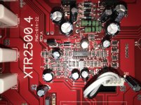
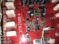
Repost with the photo taken at a slight angle so there is no flash flare in the photo. Also post a wider image.
Thanks Perry, I will scope it out and see if it it or not. In the mean time I am tracking down all the defective parts on the damaged channel. Thanks again!!
Conclusion
The intent of this post is just to document what I observed with this amp for others and future reference. The drivers and output devices were changed and the amp was working normally.
With 15.0V input, the rail voltages was +68.5V and -68.5V, so the driver and output devices saw 137V for a brief time and then it dropped down to 135V after a couple of seconds.
The amp performed as expected and was tested to thermal cycling that started from about 90 degree Celsius.
- Home
- General Interest
- Car Audio
- ORION XTR2500.4