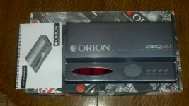
i recently acquired a Orion deq30, when i wired it up it did not turn on at all.
Opened it up and found an internal 1.5amp fuse that blew, bought another one thinking i bought it like that, and the same happened again.
so either its pulling excess current or something is shorting out.
Im not very skilful, im a 2nd year engineering student so i have a bit of knowledge but not in depth enough YET.
so im hoping someone can give me some help while i go thru it starting from the power section.
if this does not work, i am considering to sell it on ebay by next week MONDAY
wish me luck
I plan to upload a picture as soon as i find the camera, the fuse is a AGU 1.5A 250V fuse which serves to protect in the event of a power surge or short circuit,
After it i found a L7805CV voltage regulator which has a maximum output current of 1.5 Amps, how convenient lol.
description here:
L7805CV: ST MICRO: ICs & Semiconductors
My question now is how do i test it by itself to ensure it is the problem, can i remove it from the circuit board and simply test with a multimeter or do i need a power supply.
a power supply is handy. imo, one sure way is to see what happens with it removed first. if you can power, first install it without the emitter leg connected and read the voltage. if the fuse shorts, the regulator is likely at fault.
at a meere 1.5a, you likely have many odd and end power adapters/chargers laying around that could fit the bill.
at a meere 1.5a, you likely have many odd and end power adapters/chargers laying around that could fit the bill.
guess ill find an adapter and splice it.....ill do it first thing once i wake. but wait? the data sheet doesnt seem to tell me which leg is the regulator or the emitter. i need to pay more attention in school lol
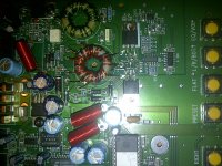
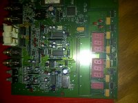
Not the best of pictures because i was using a blackberry 
neways the 4 metal pins from right to left are as follows 12V, Ground, REM1, REM2
the rem2 simply serves to add other components.
So what ur saying akheathen is to simply detach the the IC and test two feet at a time?
Ill look back on the datasheet to see which legs i need to open HAR HAR HAR.😎
neways the 4 metal pins from right to left are as follows 12V, Ground, REM1, REM2
the rem2 simply serves to add other components.
So what ur saying akheathen is to simply detach the the IC and test two feet at a time?
Ill look back on the datasheet to see which legs i need to open HAR HAR HAR.😎
Attachments
I googled it all, i feel so dunce 🙁
well i hope it all works out, then ill be running to radio shack
well i hope it all works out, then ill be running to radio shack
as far as i know, radio shack only carries the hobby level components. i get resistors and such there, but any of the egc level parts, like transistors, i would only be using for testing purposes, for reliability reasons.
i buy from digikey, but there are many sites, like tayada, arrow, mouser, etc. a google search for the part number will bring up many sites
so the Fuse did not blow, I found a ADAPTER which was 12V 1.5A it gave about 11.49V
but i did get a light which means the board has a chance,
If im correct the EQUALIZER has three sections,
-one section powers the CLIP LEDS and Digital display,
- secondly the amplification of the signal
-and the third the manipulation ie equalization of the signal
ive traced the circuit using the continuity which i then come across a IRF9540, im gonna remove the legs of it and see if the fuse blows
So! i removed two 3055VL trans and the fuse didnt blow
MTD3055VL1 datasheet | Pinouts | Circuits | Schematic for Power Mosfet 12 Amps, 60 Volts
each p3055vl has input via GATE from the tranformer
BUT unfortunate for me, The CRAP soldering iron which i bought from radioshock took out the entire joint which the legs are soldered into. It can be fixed wid some 20awg wire and some solder and simply reconnecting the points the old school way but im getting lazy now.lol
I was really looking forward to this EQ as its 30 bands and 4 presets which is really handy but im starting to wonder is the 3055 is the only problem, maybe this task is more than i bargained for and ima bit over my head,
BTW i got this of craigslist from a guy who claimed he was in IASCA back in the day, i bought it for $50 and never tested it because i was in a rush..........what a waste.
Anyways, ill update if i put this up on EBAY AS IS.
do an ohm check on the 9540. that is a common transistor used in outputs, and could likely short if damaged. it will also likely be driven by a smaller single transistor, or the regulator. if the 9640 is shorted, then removing it should allow the board to power up fine. how did the regulator do for output? without seeing the circuit, i cannot say how everything is setup, but generally, there is a power management that runs regulated to the op-amps, and output devices. then there is the "processing", you could say, which you can separate into blocks on a diagram. i see torroids, though, and there may be much more to it. look over the circuit to see how it is all setup. how is the transformer used? at this point, you can see 10x more of it than i can, lol.
oh, i see, now. those look to be what drives the power supply. ohm check those for shorting. perry babbin has links in his sig to his sites, that describe the testing procedures for them. you will want to check the signal fed to those, as well, and replace the gate resistors, if they are bad. had i known there was a power supply section like that in there, from what it looks like, this is the first place i would send you. however, if you got it to power with the regulator removed, this may point at something else. where in the circuit is the regulator?
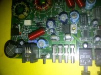
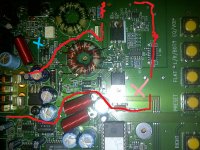
its night time where im at, so i apologise for the bad lighting
A is the voltage regulator,
B is the IRF 9540
C are the 3055VL
A is the voltage regulator,
B is the IRF 9540
C are the 3055VL
Attachments


yah, working with a non-regulated soldering iron takes a little tact, and tentative approach. key to keep it real clean and freshly tinned, and heating just off the pads to let the heat hit the joint more even. plunger solder sucker does wonders and helps to not over-heat the pads. then there are some pads that just don't like to behave, lol. anyways, i cannot see the power flow, but it looks like the 9540 controls the positive power side, then it goes through the inductor/choke with the green wire, and the 3055's are the basic switching devices run directly form u65. i see 2 pairs of secondaries, and i cannot tell for sure if the regulator runs off the secodaries, since it is sitting right at the positive power, but also has the secodary power directly on the other side. if it does run from the secondaries, and lifting the output leg stops the draw, then the power supply section should be working fine. if it runs directly from 12v power, then check if the power supply will activate and idle with the leg lifted. the 3055 fets should be getting something like 30k/60khz @5v and 40-50%duty cycle.
ohhhhh an oscilloscope....if only i had one close by.
if it does run from the secondaries, and lifting the output leg stops the draw, then the power supply section should be working fine
which thne means i have bigger problems?
then check if the power supply will activate and idle with the leg lifted
I dont understand what you meant by activate and idle, without an oscilloscope what else can i check.
since the pads fell out and it slightly damaged the point leading to the pads im kinda bummed out now caus the points wont even connect, if i was @home or school id have all the right equipment.
im currently in alabama, thats why im considering EBAY at the moment,
but if i have a chance of fixing this i might just throw it into my RIDE and add to my goodies
ahhh thanks for the help btw......ur the only guy who cares in this section lol
because this piece is a bit old skool and complex, im starting to worry that if its not within the power supply section it might be over by the digital display side.
what i can say so far is that by detaching the emitter leg of the regulator, a light turned on over by the processing sector. then by removing the leg of the IRF DRAIN the light then turned off.
im tempted to buy the tutorial CD from BCAE1....ive always loved that website
Attachments
Last edited:
if you have access to a fluke 87, or similar model, you can get by with checking for switching. you won't be able to actually see the signal, but you can verify hz and duty cycle. truth be told, that is what i am relying on on the bench, until i get my scope fixed. i would also not say i am the only one who cares, either, just timing. there are several on here, especially perry, who are extremely helpful, and i would say more experienced than i.
i digress. anyways,
have you mapped the power flow to see how it is set up?
have you ohmed/checked the 9540?
if the 9540 is how i described, then lifting it would certainly shut the power off.
by "activate and idle", i simply mean that it turns on and stays on without shutting down, or pulling excessive current.
one other thing to check would be the rectifier diodes (d59, 58, 57, 56, and i assume 55/54.) the 6, looks like.
right now, we are just shooting in the dusk until you go through the footwork of tracing how all the components are working together.
don't suppose you searched for the schematic of this unit yet, did you?
- Status
- Not open for further replies.
- Home
- General Interest
- Car Audio
- Orion DEQ30