I don't think the leakage (well into the M-ohms) that you're seeing could cause any significant problems.
What concerns me is that the 6491s are/were getting hot enough to fail while the 6488s were remaining cool. Having more 6488s could make a bit of difference but so much that they would remain completely cool. From the emitter resistor values, it would appear that there was current flowing through the 6488s which should make them heat up.
Do you have positive rail voltage on the emitter resistors for the 2N6491s and negative rail voltage on the emitter resistors for the 2N6488s? Check this with all output transistors out of the circuit.
Measuring rails with -probe on the negative speaker terminal and +probe on the unpoppulated emitter pad: +19.5V on the 2n6491 and -30.5 on the 2n6488. This matches the voltage measured directly across the big caps in the middle of the board as well.
The positive and negative voltage should be the same. Could you possibly have a bad connection on one leg of the positive rectifier?
Confirm that you read 0 ohms between the outer legs of the rectifier.
Confirm that you read 0 ohms between the outer legs of the rectifier.
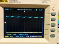
Connections look fine. Measures 0.00V from pin1-3 of each rectifier. Also measures .7V using the diode check tool on the DMM for all 4 diodes (2 per chip). I hooked up my scope to see if there was anything going on and found that there is a good deal of ripple happening on the positive rail but not the negative rail. It's at about 8Hz. This is still with no output transistors installed.
Scope is negative terminal on the gnd of the caps and probe on the middle pin of each rectifier.
Scope is negative terminal on the gnd of the caps and probe on the middle pin of each rectifier.
Attachments
This thing has so many problems...
The op amps have no VCC-. Maybe the 337 I put in there was the wrong part or it's blown? Also, is there supposed to be 12V on the collector of all outputs?
The op amps have no VCC-. Maybe the 337 I put in there was the wrong part or it's blown? Also, is there supposed to be 12V on the collector of all outputs?
We can work through the various problems. What is the DC voltage on all legs of the 337?
No. The voltage on the collectors should be close to 0v.
No. The voltage on the collectors should be close to 0v.
Measurements are between common terminal of 4 large caps in the middle of the board and the respective chips pin (1-3)
LM317: 12.5 13.75 18.75
LM337: 0.57 0.01 0.63
Collector outputs show 12.5V one channel and 11.5V on the other channel. (All pin2)
LM317: 12.5 13.75 18.75
LM337: 0.57 0.01 0.63
Collector outputs show 12.5V one channel and 11.5V on the other channel. (All pin2)
That appears to be shorted to your 12v power supply. What's the resistance between the 12.5v center leg and the B+ wire feeding the amp (disconnect the amp from everything else)?
There are two 5.6 ohm resistors near the center of the board. One may be open preventing the negative regulator from having any input voltage.
Your pretty smart Mr. Babin. One of the 5.6 ohm resistors was open which supplied the 337 which regulated the negative rail and all the op amps. Once I replaced that I now have ~23V rails for both +-. I reinstalled one channel of outputs and measured for voltage amplification and it works perfect. At full gain its a voltage gain of 100. Clips at the rail voltages. Seems to work perfect. Tomorrow I'll install the other outputs and put it back in the heatsink to really test it out.
what diode do you recommend for the reverse protection on the power input? Does it need to be high enough current rating to allow the fuse to pop? So like 80 amps?
SUPER THANK YOU!
what diode do you recommend for the reverse protection on the power input? Does it need to be high enough current rating to allow the fuse to pop? So like 80 amps?
SUPER THANK YOU!
- Status
- Not open for further replies.
- Home
- General Interest
- Car Audio
- Orion 250 HCCA repair help