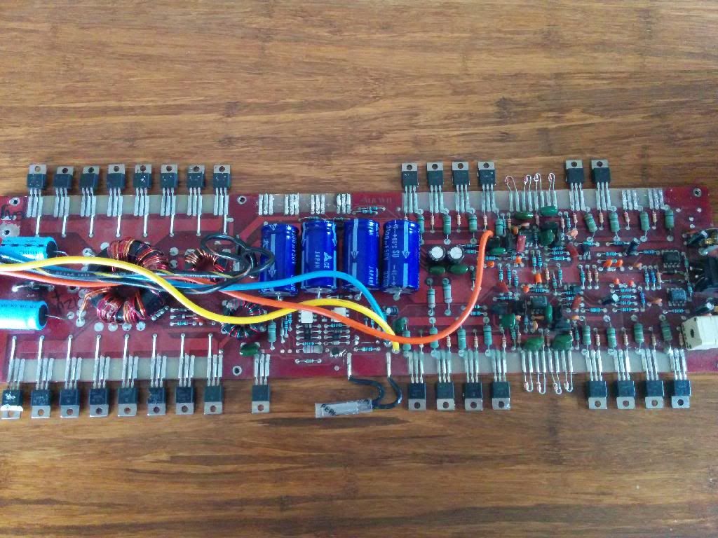
Hey guys first post here. looks like a great forum. I'm a BSEE student and I inherited a few busted Orions that somebody had "attempted" to fix. That means I'm fixing other peoples mistakes and I can't trust current parts that are on the board.
First gen 250 HCCA. I'll take pictures shortly. I'm going to replace all the 2n6488 in the power supply and all of the output transistors as well (2n6488 and 2n6491).
1) Its missing the four TO-220 parts that are between the power supply and output fets. There is no silkscreen but there is + and - markings. I think these are supposed to be voltage regulators but I don't know what the part numbers are since they are missing.
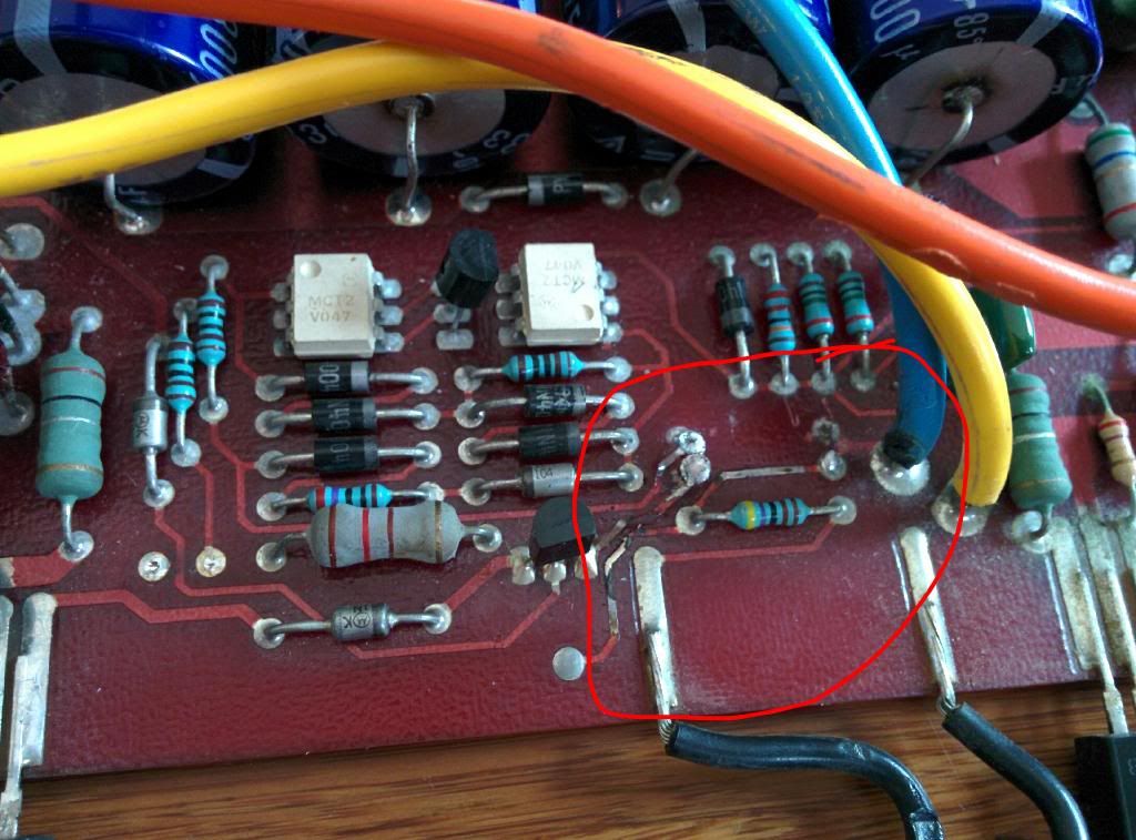
2) Its missing some parts on the opposite side of the board that were removed. I'm guessing diodes. I need part numbers for those as well. I wish there was a silk screen with part designations. Its the two diodes that reside next to the remote turn on wire.
First gen 250 HCCA. I'll take pictures shortly. I'm going to replace all the 2n6488 in the power supply and all of the output transistors as well (2n6488 and 2n6491).
1) Its missing the four TO-220 parts that are between the power supply and output fets. There is no silkscreen but there is + and - markings. I think these are supposed to be voltage regulators but I don't know what the part numbers are since they are missing.
2) Its missing some parts on the opposite side of the board that were removed. I'm guessing diodes. I need part numbers for those as well. I wish there was a silk screen with part designations. Its the two diodes that reside next to the remote turn on wire.
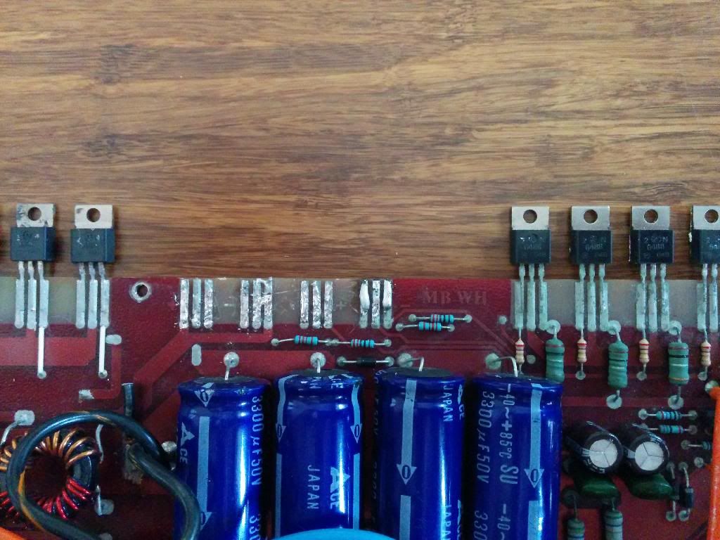
The 4 missing components on the top of the board are likely two rectifiers and to the right of those, two voltage regulators (LM317 and LM337?).
I don't know what the other components are.
I don't know what the other components are.
Looking at the second pic, it looks like the first two spots are for the rectifiers (MUR1620CT/CTR) and the second two spots are for the voltage regulators (7815/7915). Again this is just what I believe goes in those spots, am pretty sure someone with one will confirm the components.
Perry knows a way lot more than me so I would take his advice, I was going off of a PPI design that looks pretty similar.
Perry knows a way lot more than me so I would take his advice, I was going off of a PPI design that looks pretty similar.
The reason that I assumed that they are the 317/337 is because there are adjacent resistors. If they are 7815/7915s, the center leg of the positive reg will be directly connected to the first leg of the negative reg.
OK so I made some progress.
1) Replaced all 16 of the 2N6488 in the power supply section
2) Populated the 4 missing locations (left to right) with U1620G, U1620RG, LM317, LM337
3) Replaced all 4 of the PNP 2N6491 on one of the channels
4) Populated the two missing diodes with 1N4007. Polarity is per image found online.
5) Replaced visibly dead reverse power protection diode with a 1N4007 (probably need something bigger for this application)
Observations:
Powered by a computer PSU, 12.6V across input power terminals when remote disconnected.
1) As soon as I turn on (remote->12V) the PSU shuts off (protection mode, PSU spec is 18A)
2) Insert a 0.6 ohm power resistor in series with +12V, then turn on, amp makes audible buzz (guessing around 500Hz, sounds like it's from the transformer) and the supply voltage drops to 5.6V. Ammeter in series with power shows a 6A draw when connected in this config.
I want to take voltage readings around the circuit but I can't get a stable power supply. Do I need to remove all the output BJTs to troubleshoot the power supply?
Ref: the image I used for polarity of those missing diodes: (This is not my amp)
http://i1232.photobucket.com/albums/ff372/skibum_jr/DSC01377-1.jpg
Last edited:
Which of the heatsink mounted components get hot when it's trying to power up through the resistor?
None of them get hot. Though I have the clamped down with the big aluminum bar so they would have to get very hot to get that thing warmed up.
Taking some measurements. I find that the 2N6488 on one channel shows:
07.V Base-GND
1.4V Emi-GND
on the other channel the 2n6488 shows
1.4V Base-GND
1.4V Emi-GND
Note that these are the output BJTs that were not replaced.
Taking some measurements. I find that the 2N6488 on one channel shows:
07.V Base-GND
1.4V Emi-GND
on the other channel the 2n6488 shows
1.4V Base-GND
1.4V Emi-GND
Note that these are the output BJTs that were not replaced.
no component designations to help but a bunch read >0.000. I got everything from 0.000 on some all the way up to .12V on others. A few of the 2N6491s also show voltage on their emitter resistors. I have the parts on hand, maybe I should just replace all of the transistors that I haven't yet replaced?
The ones with more than 0.000v are the ones passing current and causing the high current draw. I'll need a photo showing the voltage on the ones higher than 0.000 to be more precise.
OK so I removed all the output transistors and was able to get the thing to power on using a limiting resistor. Still draws 6 amps. Noticed that one of the power supply transistors (a 2n6488 seperate from the rest of the PS) was getting hot. I removed it and voilla I get a stable power supply drawing only .04 amps when idle. This is with the outputs still removed. So I replaced that transistor and again it shorting out. So something connected to this transistor is drawing current. But what?
Here is the picture of the circuitry in question. Do I need to remove the large resistors to test for a short?
Note that I had to work with lifted PCB traces shown in this pic. I'm not sure if this is due to the original damage or if this was due to the previously attempted repair.
Note that I had to work with lifted PCB traces shown in this pic. I'm not sure if this is due to the original damage or if this was due to the previously attempted repair.
Attachments
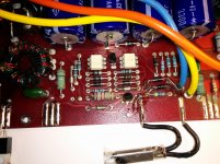
I'm suspecting the MPSA06 between those white op amp looking things and the other shown at the bottom of the circuit board next connected to the zener can.
I just ordered some, they'll be here tuesday.
Edit * wondering what would happen if I stuck a 2n3904 in those spots.
I just ordered some, they'll be here tuesday.
Edit * wondering what would happen if I stuck a 2n3904 in those spots.
Last edited:
Nope, 3904s didn't fix the problem. I replaced the MPSA06s with 2N3904 and replaced this questionable transistor and it draws 6 amps at idle again.
A couple of notes...
These amps do not like power sources with too much resistance. They will draw excessive current. That may not be your problem but it's something that you must consider.
The transistor that you removed in the power supply drives voltage to the driver transformer so the power supply is doing nothing with it removed.
In the future, remove the rectifiers before you remove ALL of the output transistors.
The only output transistors that should have been removed (causing the excessive current draw) were the ones with more than 0.000v DC across the emitter resistors.
-----
Do you read 10 ohms between the collector of the PNP power supply driver transistors and ground?
Perry, thanks for all your help. You are awesome.
Test PSU - Is there a better solution than the SMPS i'm using? Maybe it would be better to use a car battery? I appreciate the short circuit protection on the SMPS though so I'd have to possibly get a circuit breaker to connect inline.
Should I remove the rectifiers before doing anymore testing? Or are you saying that removing the rectifiers effectively disconnects the output transistors so I don't have to remove them?
PNP PS drivers - that may be the problem. They were all 2n6488 on the supply side. Maybe they were supposed to be half 2n6491s but the previous repair attempt was done with wrong parts?
Looking at the board again, this amp doesn't use the drivers that I was referring to.
As an example of how these amps behave when the supply is limited, I have a 2350 (or maybe the 4ch version) that will drive my 20 amp power supply into protection and draw a continuous 18-20 amps if I use small wire (about 2-3 feet of 16g wire) in the power line. If I use larger wire it powers up instantly and won't even blow a 5 amp fuse powering up.
When you don't know why there is excessive current draw, you can pull the rectifiers and (in most amps) that will disconnect the audio section from the power supply section. If the current draw drops, that means that the problem is in the audio section (generally).
In this amp, you found excessive voltage across several of the emitter resistors. Leave the output transistors on that side of the amp out of the circuit and confirm that you have no solder bridges between any of the solder pads. Confirm that there are no bridges with a multimeter. These boards tend to make hairline bridges along the edge of the board. Reinstall the output transistors on the other side of the amp. There shouldn't be anything out of the amp except the output transistors on one side of the amp.
Try to power it up with your computer power supply. Does it power up?
If you want to try a battery, install a 10 amp fuse in series with the positive power lead.
OK so I reinstalled one channel of outputs and used a bigger computer PSU. Now it's turning ON and lighting the LED. I didn't have it in the case with heatsink and the PNPs got hot and one of them let the smoke out. Removed that 2n6491 and left just 3 in there to try, they again are getting hot while idling.
- Status
- Not open for further replies.
- Home
- General Interest
- Car Audio
- Orion 250 HCCA repair help