I'm not sure how much I understand.
The cap is likely causing the sparking. If so, that's normal.
The transistor that you removed feeds voltage to the drive windings so there should be no drive. What is the voltage from the base to the emitter for the 6488s in the power supply? All should read 0v.
The cap is likely causing the sparking. If so, that's normal.
The transistor that you removed feeds voltage to the drive windings so there should be no drive. What is the voltage from the base to the emitter for the 6488s in the power supply? All should read 0v.
I know, sorry for my bad english..
The measures frome the base to emitter give a floating voltage, can be 1,6v or 0,1.
It's change continuously, in positive or negative voltage too.
Never stable.
Windings transistor is removed, and optos also.
Remote not connected.
The sparking happen continuously, when i put on and take off the +B continuously, one spark per second (with cap mounted)...
Thanks for diagram 90scaraudio, but i don't understand well.
Is the same of 225?
Self oscillation, i think the only one motiv.
Must i to change all power supply components?
Or need nos Motorola transistors?
I'm waiting for to have the material for some test, but i'd like to know the why about the self oscillation.
A day works ok, and the next day it turn on withouth remote...
That scheme is correct according to memory for 1G HCCA 225. Replace all actives from the remote wire to the transformer. That worked for me when I had one that would power on with no remote voltage applied.
The optos, MPS, 2N6488 of windings, resistors, diodes..
A lot of componens.
I have to get them.
Thanks.
A lot of componens.
I have to get them.
Thanks.
Optos, diodes, transistors. Check resistors for spec. Verify windings are ok. Windings should be ok.
2x MPSA06
1x 2N6488
2x 1N4003
1x 18v zener
1x 2.5v zener
The 2.5v zener anode is on base of 2N6488. 18v zener anode is on base of MPSA06. 1N4003 anodes to trafo winding, cathodes together.
1x 2N6488
2x 1N4003
1x 18v zener
1x 2.5v zener
The 2.5v zener anode is on base of 2N6488. 18v zener anode is on base of MPSA06. 1N4003 anodes to trafo winding, cathodes together.
Last edited:
The diode values are for HCCA 225. The 2.5v is common to the 2150GX but the 18v is for HCCA 225, I don't know the value for the 2150GX. That zener sets the rail voltage so will have a value that corresponds.
Are you sure that the 2.5vZ is right. I have something else but I could be wrong.
The 2150 uses two 18vZ in series.
The two diodes on the secondary (on some amps, a dedicated pair of windings) sum the output from the windings and feed the regulator's Zener.
The 2150 uses two 18vZ in series.
The two diodes on the secondary (on some amps, a dedicated pair of windings) sum the output from the windings and feed the regulator's Zener.
There may have been a change in production. I have it as a 1N4732. It's not a critical part, as long as it's intact. I just wanted to make a note of it.
Ok, thanks.2x MPSA06
1x 2N6488
2x 1N4003
1x 18v zener
1x 2.5v zener
The 2.5v zener anode is on base of 2N6488. 18v zener anode is on base of MPSA06. 1N4003 anodes to trafo winding, cathodes together.
Need time to get me the components.
I have already 2N6488 new, i must to find MPSA06 (or equivalents?), zener and diodes.
Are the two 1N4003 under the trafo? (in the diagram are the couple of 11 turn winding?)
Then i'll take the axial cap too.
I confirm 1N4732A, 4,7v-1W-5%.There may have been a change in production. I have it as a 1N4732. It's not a critical part, as long as it's intact. I just wanted to make a note of it.
I saw in other 225, in this amp impossible to read, i must to remove it.
Thanks.
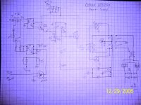
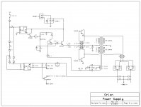
I had some time to transcribe my drawing into ExpressSCH. Anyone can download it and edit this schematic, make corrections or add part numbers.
There may be errors from when I did this 13 years ago so correct them as needed.
I can't upload the .sch file but message me and I can email it to you if you want.
There may be errors from when I did this 13 years ago so correct them as needed.
I can't upload the .sch file but message me and I can email it to you if you want.
Attachments
- Status
- Not open for further replies.
- Home
- General Interest
- Car Audio
- Orion 225 HCCA 1st gen. power supply ko