Maybe its cause this old girl isn't using a TL49x or SG352x. Seems to be a self-oscillating supply. I was able to get it powered up a few times at first on my small 5A power supply, but it took about 45 seconds to "charge up" and then it idled at about 1.5A. I played and tested with it for about 20 minutes, power cycling it a bunch of times... But now nothing. I then tried it through a 10A fuse to a large battery and it instantly popped the fuse.
I pulled a few of the rail caps and tested them. They seem to spec OK on the Fluke 16. The rects seem to be OK as well.
What am I doing wrong here? None of the transistors are shorted and I was actually able to get some audio down both channels, bit dirty; the first couple times it powered up. I believe I found a bad 10uF cap on the right channel, replaced; but now I cant get this amp to cooperate very well.
Last edited:
These amps don't like any current limiting when starting.
Try heating the terminals of any suspect caps. If any smell like antifreeze, they need to be replaced as well ans any similar caps.
Are you saying that, even on the small supply, it will do nothing?
Did it stop working before moving it to the larger supply?
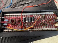
Photo of the board?
Try heating the terminals of any suspect caps. If any smell like antifreeze, they need to be replaced as well ans any similar caps.
Are you saying that, even on the small supply, it will do nothing?
Did it stop working before moving it to the larger supply?
Photo of the board?
Actually just fixed this one. Apparently these old amps like to pull about 20+amps to start up but once they do, idles back to 0.750amps. I got this one to play cleanly on both channels. The original problem was this amp would not play out of the right channel and it ended up being an open circuit through a 10uf cap just behind the right RCA.
Tomorrow I'll push it on the burn-in bench.
Thank you
Tomorrow I'll push it on the burn-in bench.
Thank you
The caps are testing -ok- out of circuit so I put them back in exactly.
I moved this amp over to high output test bench, and am finding that power-ups are no issue at all; but theres another problem.
As the volume increases, rail voltage skews off up to about 10vDC deviation, and its putting up to 10vDC out to the test speakers. Referencing center tap I see the negative side decreases from -40vDC down to about -45vDC, and the positive side decreases from 40vDC to about 35vDC. The louder I go, the worse. Speakers are being pushed out. Otherwise this amplifier is able to play and currently draws ~60A from the bench, which is staying above 13vDC the whole time.
Any thoughts as to why the rail voltage would shift and apply DC to speaker terminals by the difference in shift?
Another weird thing is, someone ran a wire to the outside of the amp, which is secondary center tap. Do I need to have that hooked up to the negative terminal during operation? Don't want to fry this old beast or anything. Photo coming.
OK on the caps. I never really saw a problem with this series of amps but it's been a while since I've worked on any. The cap problem may have started with the next series.
How much ripple are you seeing on the rails when driving hard?
What difference in voltage are you seeing between the primary and secondary grounds when you see the DC on the output?
How much ripple are you seeing on the rails when driving hard?
What difference in voltage are you seeing between the primary and secondary grounds when you see the DC on the output?
I'm not seeing much ripple I don't think. Maybe I need a lesson in exactly what you mean there?
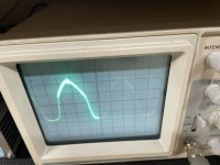
I think I did find another fault which may be causing this. The right channel (Yellow wire side) has a problem with reproducing the lower part of a sine wave. Its slightly deformed where where the Left channel looks perfect. Perhaps if I clear that up the amp will run with stable rails.
I think I did find another fault which may be causing this. The right channel (Yellow wire side) has a problem with reproducing the lower part of a sine wave. Its slightly deformed where where the Left channel looks perfect. Perhaps if I clear that up the amp will run with stable rails.
The rail voltage should essentially be a fine line that only varies with the audio waveform. With ripple, the line gets wider.
Does one channel work perfectly with no DC when driven alone?
If so, could something on the other channel be touching the heatsink?
Does one channel work perfectly with no DC when driven alone?
If so, could something on the other channel be touching the heatsink?
Are the positive and negative power supplies equal in magnitude on all op-amps?
Do you see this distortion on the input to the final op-amps in the chain (the ones that drive the output section)?
Do you see this distortion on the input to the final op-amps in the chain (the ones that drive the output section)?
Opamps are all seeing + or -14.8vDC at power pins, even under draw referencing CT. Its stable.
I'll have to trace through to answer your second question for a bit.
I'll have to trace through to answer your second question for a bit.
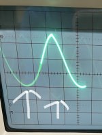
Tracing from rcas through to the opamps, the opamps nearest the rcas are looking clean on in/ouput pins, but the opamps nearest the driver transistors look like this with a pure sign wave input. Not good at all. Both channel opamps are showing this, and to be honest I'm not 100% convinced the left channel is perfect when loaded down either.
If I set my function generator to triangular wave it looks even worse than this photo. Even more crooked.
Which transistors are muting here?
If I set my function generator to triangular wave it looks even worse than this photo. Even more crooked.
Which transistors are muting here?
Attachments
Last edited:
Got it.
Leg 3 is gate of those and there are 2 of them, thats 1 per channel.
1: 0
2: 0
3: -3.250vDC <--
Then under load/draw, the left channel 2N5639 stays the same, but the right channel's drain rises up to +0.25vDC. Still -3.250vDC on both muting transistor's drains.
Leg 3 is gate of those and there are 2 of them, thats 1 per channel.
1: 0
2: 0
3: -3.250vDC <--
Then under load/draw, the left channel 2N5639 stays the same, but the right channel's drain rises up to +0.25vDC. Still -3.250vDC on both muting transistor's drains.
That's not enough. It should be about -20 in the gate.
If you pulled them, that would tell you which way to go on the repair.
If you pulled them, that would tell you which way to go on the repair.
Pulled both not to difficult. The pads are still measuring the same, -3.25vDC, 0, & 0.
The 2N5639s themselves are measuring 33 ohms between source and drains.
Surprisingly, the amp seems to be producing clean audio now, and no DC on the outputs - almost like its fixed without the muting circuit.
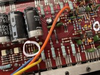
Theres a diode in the center of the board thats connected to the gates, measures -3.25vDC on one side, and -40vDC on the other side. Diode check on the PCB passes with fluke.
The 2N5639s themselves are measuring 33 ohms between source and drains.
Surprisingly, the amp seems to be producing clean audio now, and no DC on the outputs - almost like its fixed without the muting circuit.
Theres a diode in the center of the board thats connected to the gates, measures -3.25vDC on one side, and -40vDC on the other side. Diode check on the PCB passes with fluke.
- Home
- General Interest
- Car Audio
- Orion 2150GX trouble powering up