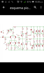
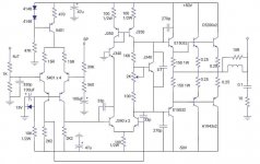
Hi Guys, I write you because I wanted to know the true origin of this amplifier which is known Pioneer Amp here but I don't think so. It is very used for home audio in these places and its sound is not so bad but some improvements can be made to this amplifier for best performance. I leave the scheme which is in your hands and suggest about it. Thanks for your attention.
Attachments
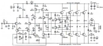
With the selection of transistors and the topology, you are likely right to assume its not original Japanese Pioneer product. It is probably a DIY design power amplifier transplanted into an old Pioneer case. Someone has already beaten you to making "improvements" (or simply fixing a dead amp) 😉
Some transistors like MJE340/350 may not be the most suitable in locations like the voltage amplifier stage (VAS) where they are often chosen for their voltage rating and low cost, neglecting the need for low capacitance (Cob). I have no idea what this design's specification called for but simply fitting more appropriate grade parts may be worth trying first.
Other than that, there are are plenty of good designs presented here that you could build and replace it with but first check that your particular needs for sound quality can be met. Not all designs are created with the same priorities and some DIY designs are too basic or ill-conceived to improve much at all. Sometimes the preamplifier and tone controls or mechanical switches, relays etc. are the actual limitation to sound quality and no amount of changes elsewhere will improve that.
Thank you finch. I suppose well: this amplifier is not Pioneer's.. I know there are many amplifiers better than this one. I had been thinking of improving it but maybe it will be better for me to build one of the amp posted here.
On the other hand, this one can also be better than plenty of designs presented here. I would try to increase the current in the output transistors.
Yes, a bias of only 2 diode junction voltage drops is low for an emitter follower design with standard planar bipolar transistors like C3858/A1494. Even so, I would not fit more than 3 silicon diodes in series without carefully monitoring the bias stability over the full temperature range. The diodes should also be in thermal contact with the heatsink (but electrically isolated) to avoid thermal runaway.
A better solution is to design and fit a proper, adjustable Vbe multiplier circuit since when testing, it's all too easy to destroy an amplifier or at least the power transistors, if the current is fixed. Incidentally, the large Sanken transistors are now obsolete and soon will become rare and a lot more expensive. I'd take care with them even if they are not the best LAPT type. 3 pairs of output transistors (I assume from the partial schematic) could make quite a powerful amp. What are the power supply rail voltages?
A better solution is to design and fit a proper, adjustable Vbe multiplier circuit since when testing, it's all too easy to destroy an amplifier or at least the power transistors, if the current is fixed. Incidentally, the large Sanken transistors are now obsolete and soon will become rare and a lot more expensive. I'd take care with them even if they are not the best LAPT type. 3 pairs of output transistors (I assume from the partial schematic) could make quite a powerful amp. What are the power supply rail voltages?
Hi N101N and Finch thanks for answering. This amplifier is being supplied with +/-75Vdc and eight Power transistors (four per rail) are connected in the final output stage. Yes, a Vbe multiplier can be added instead of the two diodes in series for best Bias sense monitoring. I would also like to change the voltage source by a constant current source for the differential pair. I will wait for any suggestion from you. Thank you for your attention
Those voltages are far too high to my taste, making decent biasing and distortion reduction impossible. I have lost interest in the project.
By the way, are those transistors genuine Sanken?
By the way, are those transistors genuine Sanken?
Yes, these transistors are genuine from Sanken. As I said, I think if we make some changes to the amplifier maybe we'll improve its stability. But you are the masters!
Better add a bias-stopper to VR1. When VR1 is turned to a very low value, the biasvoltage will raise to considerable values causing Q13 -- Q20 to run in 'high class A' setting.
So, change VR1 from 5klin to {5klin + 1k0}; Vbias max is limited to some 3.4V.
So, change VR1 from 5klin to {5klin + 1k0}; Vbias max is limited to some 3.4V.
An improved version of this amplifier.
I think the zener diode current source circuit is not so good, a fail of the 100uF cap will make big noise to the output.
The simple two trasistors current source circuit is much more stable to replace the zener diode circuit(in red area).
Attachments
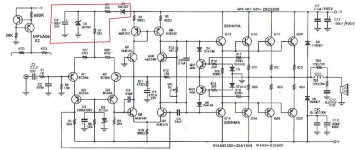
Hello Mars. Thank you for replying. I drew another schematic in which I made some changes to the resistors of the Vbe transistor's base putting a stopper to VR1 to prevent the output stage from any thermal runaway after turning VR1 to minimun value. I also added a current source for the differential pair. I tested the amplifier for some hours and the sound is very good.
I think the zener diode current source circuit is not so good, a fail of the 100uF cap will make big noise to the output.
The simple two trasistors current source circuit is much more stable to replace the zener diode circuit(in red area).
Hello Patrick101. Thank for your suggestion. I also changed the zener diode circuit for a current source as I said in my last message. I tried to upload the diagram with the changes I made but my cell phone does not allow me to do it. Any suggestion, Patrick and rest of community, welcome!
I also changed the zener diode circuit for a current source
Sorry, I just look at the schematic and did not notice you make quite good changes in your amp.
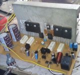
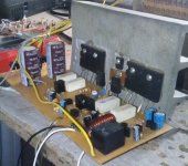
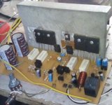
Could you upload pics of your amp, let us know your amp's layout
Thanks
Patrick
Hello Patrick. I have been trying to upload two pics but the cellphone or the website (I don't know) doesn't allow me to do it. Sometimes I can upload several photos but sometimes I can't. There is a message that says Poor memory to perform this action.Sorry, I just look at the schematic and did not notice you make quite good changes in your amp.
Could you upload pics of your amp, let us know your amp's layout
Thanks
Patrick
- Home
- Amplifiers
- Solid State
- Origin of Unknown amplifier.