Withing the operating range, about 337 mA during start-up, the voltage out of the regulator will see a drop of less than 40 mV. the power supply itself, less than 60 mV. Steady state current draw is under 180 mA.
The PSU is able to provide 800 mA of current but with a 140 mV drop in voltage I measures the REG Board up to 700 mA with a 60 mV drop in voltage
The PSU is able to provide 800 mA of current but with a 140 mV drop in voltage I measures the REG Board up to 700 mA with a 60 mV drop in voltage
Last edited:
I replaced all the components on the motor except the Tantalum capacitors. The resistors are TC and Vishay-Dale low PPM metal film. The round Pot is now seal. The speed adjust Pot are Vishay precision. Also added are a cap at the power input and caps at the speed pots.


I turns out a considerable percentage of the voltage drop is from the 5 foot 22 g cable. At the power supply the drop is negligible. I have ordered and received 14 g cable with shielding foil and wire from McMaster Carr. Only place I could find at 10 ft length and fast delivery. Will post the results soon. SO the stock cable from the oracle supply is not 100 % sufficient!
SOTA used the Papst motors and yours looks the same.
I didn't,t know Oracle used the same motor?
Regards
David
I didn't,t know Oracle used the same motor?
Regards
David
Hello David,
Yes its's he GS 38.09. There is a schematic out there but it is for the very 02 PCB on the motor. I have Ver 01. Believe goldmund and a couple others used this motor back in the day.
Yes its's he GS 38.09. There is a schematic out there but it is for the very 02 PCB on the motor. I have Ver 01. Believe goldmund and a couple others used this motor back in the day.
A comparison of the stock 22 gauge umbilical cord with the new 14 gauge. The rated maximum load is 0.5 Amps, but the load for the test was performed up to 0.9 A. The results are much better. I will do a new load chart out of the regulator next.

The regulator PCB was tested with the new umbilical and is now voltage constant out to 600 mA of load.

Next the system was measured with a +/- 10 % (108-132 VAC) variation on the mains. The supply-regulator is constant to my goal of a 500 mA load with a 2 dB head room under normal mains conditions.

Close enough for rock-n-roll. I will now put it together and move on to a sub-chassis design.
One note: It appears a quick tweak for those with a standard Oracle power supply would be to change out the umbilical cord from the stock 22 gauge to a 14 gauge. I can provide the parts numbers needed and vendors. Less than $20 to DIY.
One note: It appears a quick tweak for those with a standard Oracle power supply would be to change out the umbilical cord from the stock 22 gauge to a 14 gauge. I can provide the parts numbers needed and vendors. Less than $20 to DIY.
Last edited:
On an earlier effort I had plated the motor clam shell with black nickel essentially making it a constrained layered structure and making it look cool to me. This time I spayed the inside with damping material just for added vibration damping.


Next, The motor was put together. I have designed to mounting to have mass and also compliance thru damping mounts. The center of mass is displaced to slightly pull against the platter via the belt.
.jpg")
.jpg")

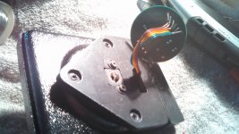
The wiring from control to reg board to motor: (Note: the kapton tape under the Reg PCB is really important. This is the second board. I zapped the switch transistor)
.jpg")

.jpg")

.jpg")
.jpg")
Attachments
Last edited:
Finally a quick live test and final assembly. I should note, i used a stethoscope i found on my lawn once. I listened at the motor and at various points on the Plexiglas chassis. There was a noise which was not audible to the naked ear. I simply adjusted the thrust screw on the bottom of the motor. The noise is completely gone to the stethoscope at least.

.jpg")
I have been working on my new sub chassis. My goal is to come in less than what it would cost to buy one directly. I have chosen to go with constrained layered aluminum monocoque tying the spindle bearing to the tomearm mount. It will also extend out to the pillar arms for rigidity. The rest of the sub-chassis will be 3D printed with ABS (So I can plate it). The ABS will have 5 mills of black nickel for a big increase in stiffness. Inside it will act and an additional path for energy to escape ton the top layer aluminum.
I have the initial layout done. I had added an tonearm load (SME V) and an equivalent load from the belt. Here I assembled the current iteration leveled it put a dial indicator and attached the belt. I then added weight until the dial indicator zeroed. I did some FMA to look at the deflection of the pillar arms versus the current Oracle sub chassis. With the Nickel plate, it is actually slightly stiffer, but we are talking less than i mill deflection. With my FMA suite I cannot do nonlinear analyses needed to model the constrained layer. I will do this will another software now that I have a basic design. For now, The center of mass is at the bearing rid on level with the bottom of the platter and the stiffness is high.
I have the initial layout done. I had added an tonearm load (SME V) and an equivalent load from the belt. Here I assembled the current iteration leveled it put a dial indicator and attached the belt. I then added weight until the dial indicator zeroed. I did some FMA to look at the deflection of the pillar arms versus the current Oracle sub chassis. With the Nickel plate, it is actually slightly stiffer, but we are talking less than i mill deflection. With my FMA suite I cannot do nonlinear analyses needed to model the constrained layer. I will do this will another software now that I have a basic design. For now, The center of mass is at the bearing rid on level with the bottom of the platter and the stiffness is high.
- Home
- Source & Line
- Analogue Source
- Oracle Delphi MK II Mods