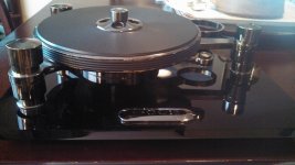
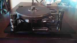
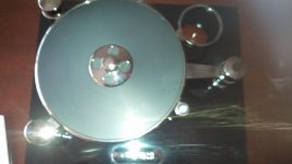
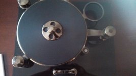
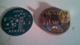
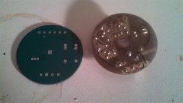
I have been modding my Oracle Delphi Mk II for years. I while ago I modded the control electronics, the motor mount and the bearing. BTW, the Oracle bearing system is not new. It has been used in optics for precise laser mirror rotation. There is a patent for it 6 point bearing system.
I am going to redo the sub-chassis so I will share this info later.
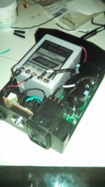
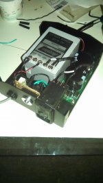
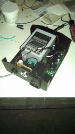
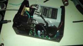
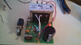
I will start with the power supply. I have the most current, but non turbo supply. The exorcise was to fit a supply in the same box because I think it looks cool.
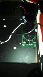
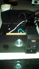
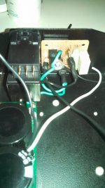
I had a lab style supply laid out, but then found an Acopian supply on eBay for 40 bucks. I went with the Acopian and added a filtered power entry module, design a PCB for a DC blocker which would fit the block and finally a ground loop breaker for which I added a perf board for the resistor and capacitor.
Next I plan to replace the local regulator with one using the new TPS7A4701. It's specs look really good, especially in the low frequencies compared to the LM317 used.
I do have schematics of the original electronics and my modded ones if anyone is interests. They were made by tracing out the old PCB's.
one more thing, I will be replacing the caps and resistors on the motor PCB. There is a schematic out in the internets GS 38.09 Ver 02. It is more extensive than the Ver 01 which I have. If anyone has experience with the difference and can give some pointers, it would be great.
The following PSU will be running between 27.04 and 28 Volts. The GC 38.09 is spec't for 27 +/- 20%. Steady state current draw is 45 mA, transient is 240 mA. The light bulbs and LED suck up less than 100 mA more. The Acopian I a using can provide 1/2 Amp.
Last edited:
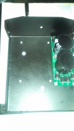
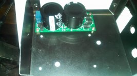
I laid out the parts in solidworks so I could place all the components and they would fit. This mechanical layout was also used to determining the size of the DC blocker PCB.
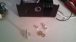
mod to the box are as follows:
1) Punching out the three weldnuts for the old PCB mounting
2) Drilling 8 through holes for the Acopian and DC blocker
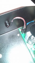
3) in the area of one of the cable entries, a cut out for the IEC was made
4) In the area of the Fuse holder (the center hole) a spot face was made for chassis ground contact.
Machining time was about an hour. this would mean a cost for $60 to $85 depending on your machinist.
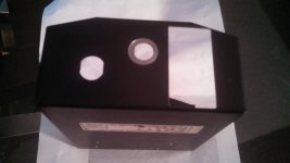
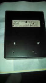
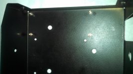


Last edited:
I will be running a few tests at work after I enlist the help of one of our test engineers. Will post the results.
Interesting, I have a MKII that I bought in '86 and for a variety of reasons it's never been used.
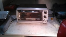
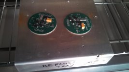
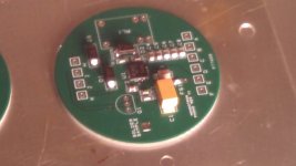
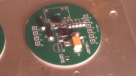
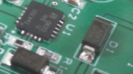
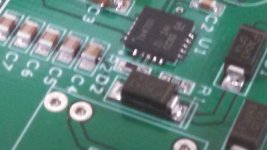
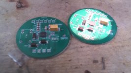
Loaded the regulator PCB. Used a needle on a stick,a syringe, a microscope, an ESD strap and coat, and a toaster oven:
When Applying the solder paste I used a needle in a stick, which is what we use for applying adhesive on micro optics. The rules of thumb for solder paste is the soldered thickness will be half the applied paste thickness. Less is more! especially on the thermal pad of the TPS7A4701. The same goes to the lease of the IC and any really small resistor or capacitor. The rest I used the needle that cam with the syringe.
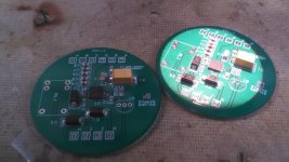


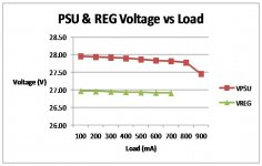
I tested the PSU and Reg board last night using the Tindie R:Load . The R:load is a cool little circuit that allows you to dial in an active load, or current sink. The EE's at work have hijacked it. I left my mem stick at work so I am just posting the voltage data now. We do have this cool box that will measure spectrum from .5 Hz into the 10's of GHz/ But alas, it can only take a maximum input of 5V - Bummer! So I used another O'scope with FFT capability. Unfortunately it does not got deep into the audio range. The FFT was pretty flate though. When reducing the V/Div on the scope, I encountered a noise floor of about 5 mV with spurious signals at 10 mV. This is most likely from the tons of RF equipment surrounding this test and all the hook-up leads. Will post later.

- Home
- Source & Line
- Analogue Source
- Oracle Delphi MK II Mods
