overcomplcating a tonearm.
All,
simpler really is better.
DD:, your idea has some merit, but anything that rides above the pivot point(s) is inherently unstable. Hang the mass, don't try to "push it up".
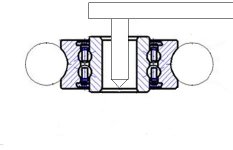
Perhaps there is a solution that is even simpler. Get a piece of Teflon (the real thing). glue to a horizontal bar. Etch or score the Teflon with a horizontal line. Take 2 high precision ball bearings (.1mm or less), and attach them to small vertical shafts which attach to a horizontal "carrier". The horizontal carrier then attaches to a vertical piece, which becomes a location to attach the counterweight and tonearm shaft. The arm then rides on the little ball bearings horizontally while being free to pivot.
All,
simpler really is better.
DD:, your idea has some merit, but anything that rides above the pivot point(s) is inherently unstable. Hang the mass, don't try to "push it up".
Perhaps there is a solution that is even simpler. Get a piece of Teflon (the real thing). glue to a horizontal bar. Etch or score the Teflon with a horizontal line. Take 2 high precision ball bearings (.1mm or less), and attach them to small vertical shafts which attach to a horizontal "carrier". The horizontal carrier then attaches to a vertical piece, which becomes a location to attach the counterweight and tonearm shaft. The arm then rides on the little ball bearings horizontally while being free to pivot.
Hi,
I think the main problem with those engineering solutions is that the contact area is just too large, too dispersed.
Basically you'd like to mimic a mechanical diode, i.e. creating a preference path of low mechanical resistance that evacuates vibrations created by the cartridge/tonearm interface and at the same time make it hard for those vibrations to travel back to the source.
I could and have in fact developped this engineering theory on this forum before. I guess the relevant info is tucked deep in the archives by now...
If needed I could rehash this if you guys are interested.
Cheers, 😉
I think that with air or magnetic arms or tables for that matter you have an unfortunate disconnect and compliance issues which are easily dealt with in a mechanical design but not so otherwise.
I think the main problem with those engineering solutions is that the contact area is just too large, too dispersed.
Basically you'd like to mimic a mechanical diode, i.e. creating a preference path of low mechanical resistance that evacuates vibrations created by the cartridge/tonearm interface and at the same time make it hard for those vibrations to travel back to the source.
I could and have in fact developped this engineering theory on this forum before. I guess the relevant info is tucked deep in the archives by now...
If needed I could rehash this if you guys are interested.
Cheers, 😉
Directdriver: thanks for the excellent idea. I like the out of the box thinking going on here. Stew is right in that hanging the arm is a better way to go. Your brain has got a train on tonearm designs go man go.
Frank: are you are referring to the Cantus style bearing assembly or to air /magnetic versions? Moray James.
Fred: can you post a link or pictures of Tom Fletcher's Radial tracking unipivot arm? I cannot find anything on line. Thanks.
Hi,
I wasn't refering to any particular design nor any design in particular...🙂
Unfortunately I am not intimately familiar with any of the design approaches of the Opus3/Rauna family of tonearms.
Just pointing to some sound engineering solutions we applied back when we were of a bunch of enthusiastic engineers striving to extract the utmost of what we had way back then.
The odd number of contact points and the mechanical diode principle are ideas you can apply to any tonearm design be that tangential or otherwise.
Later on we suggested the same idea to speaker mounting, speaker to floor interfacing, etc.
Surely you do remember tiptoes, spikes, etc.? Same thing even though tiptoes and spikes aren't if you catch my meaning...
Anyway, should you feel it's redundant or irrelevant news, I'll keep out of this thread. No probs. 😎
Cheers, 😉
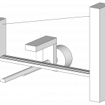
Here's another thought in my head. If I use two round rods in parallel on the horizontal plane, I can use two U-groove bearings gliding laterally without any vertical movement. And then I can place a dual-pivot housing with two spikes and an armwand.
I may misunderstand your intent, but it looks like the bearing would roll on one rod and slide on other.
Sheldon
.
If I place the spikes below the mid-point plane of the rods, then the mass is hung.
I can't visualize the teflon solution yet perhaps you can draw up something for me? Thank you and always appreciate the suggestions.
.
Nanook: "anything that rides above the pivot point(s) is inherently unstable. Hang the mass, don't try to "push it up".
If I place the spikes below the mid-point plane of the rods, then the mass is hung.
I can't visualize the teflon solution yet perhaps you can draw up something for me? Thank you and always appreciate the suggestions.
.
Attachments
Frank: sorry I called you fred my fingers don't always make sound contact with my brain. I am sorry if I gave you the impression that I was not interested in you ideas I am. Yes I follow you regarding the mechanical diode principle. I am not clear what you were referring to when you mentioned "those engineering solutions" in post #122. I think that a hard mechanical contact has distinct advantages over an air or magnetic (floating) bearing. With a non contact bearing there is compliance at some frequency which may cause issues and damping becomes more complex to deal with. I think that you were referring to air and magnetic solutions is that correct? If so then we are on the same page.
Frank are you familiar with the relationship between hardness and friction? I would like to understand what the impact is of making a bearing harder and the affect that has on friction and at what point do you reach diminishing returns. For example the glass tube in a Cantus is about 6.5 on the Mohs scale of hardness and the bearing is probably 25 - 35% harder. Would increasing the tube hardness to say the same hardness as the bearing result in a significant decrease in friction? Is it ideal to make both contacting surfaces equally as hard? Any thoughts would be welcome. Thanks regards Moray James.
Frank are you familiar with the relationship between hardness and friction? I would like to understand what the impact is of making a bearing harder and the affect that has on friction and at what point do you reach diminishing returns. For example the glass tube in a Cantus is about 6.5 on the Mohs scale of hardness and the bearing is probably 25 - 35% harder. Would increasing the tube hardness to say the same hardness as the bearing result in a significant decrease in friction? Is it ideal to make both contacting surfaces equally as hard? Any thoughts would be welcome. Thanks regards Moray James.
Sheldon: "I may misunderstand your intent, but it looks like the bearing would roll on one rod and slide on other."
You are right! Obviously my idea was not well thought out. D'oh! Thanks for the correction. The only way to make it roll smoothly without vertical movement is to have three bearings to create a triangle carriage for the vertical bearing. But by that point, it might get too complicated and very much simulated the Souther approach. Duh! 🙁
Back to the drawing board again!
.
I did not notice that small problem either but I was thinking about two small v-grove bearings to make up a composite bearing for each of the two bearings you used. So there would be a separate bearing to roll on each rod.
Sheldon: "I may misunderstand your intent, but it looks like the bearing would roll on one rod and slide on other."
It would require something like this. A triangle carriage on two rods, probably too heavy.
An externally hosted image should be here but it was not working when we last tested it.
Good Evening, all,
Nanook: Would larger bearings maybe ride over dirt and track imperfections better than tiny ones? Think 13" wheels compared to 17". Are cupped single bearings available?
DD: Making the tricycle light is possible. The rails will have to be aligned fairly precisely so the tricycle rolls freely but is stable. It's doable. Attractive idea.
Frank DeG: I'd appreciated any light you can shed on how to deal with resonances. The idea of a mechanical diode is intriguing and I'd like to hear more.
moray james:can you post a link or pictures of Tom Fletcher's Radial tracking unipivot arm?
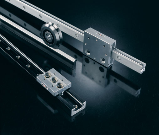
I disassembled a Nottingham unipivot arm once and saw the inner working of its design. Inside the bearing housing, there are two metal rods, below the single pivot point, that park on a ball bearing that allows the arm to move horizontally and vertically but inhibit azimuth movement. There are many hybrid unipivot arms out there that use a ball bearing to stabilize the azimuth, like the Basis Vector, Continuum Copperhead, Graham Phantom, etc.. but they all have only two contact points, whereas the Nottingham has three.
An externally hosted image should be here but it was not working when we last tested it.
The one arm that is closest in design concept is the clever Simon Yorke tonearm (Now, there's a designer whom I really admire!) that uses no ball bearing at all but uses a teflon sleeve with a guiding plate. Check picture of the tonearm from the S-9 model record player. I think the SY design is much simpler and more elegant. I also like his Bauhaus styling. Sorry to be off topic again. My mind is always at tangents. 🙂
An externally hosted image should be here but it was not working when we last tested it.
.
.
Maybe something like this, by having the two rods touching each other to avoid alignment problem or simply replace the two rods with one flat piece.
.
dtut: "Making the tricycle light is possible. The rails will have to be aligned fairly precisely so the tricycle rolls freely but is stable."
Maybe something like this, by having the two rods touching each other to avoid alignment problem or simply replace the two rods with one flat piece.
An externally hosted image should be here but it was not working when we last tested it.
.
Let's steal some DIY ideas from another forum!
http://www.hififorum.nu/forum/topic.asp?TOPIC_ID=60946 in Norwegian
http://www.hififorum.nu/forum/topic.asp?TOPIC_ID=60946 in Norwegian
An externally hosted image should be here but it was not working when we last tested it.
An externally hosted image should be here but it was not working when we last tested it.
An externally hosted image should be here but it was not working when we last tested it.
Hi,
Here's a link to what I was refering to:
GOLDMUND - Technology - Mechanical Grounding
Cheers, 😉
Frank DeG: I'd appreciated any light you can shed on how to deal with resonances. The idea of a mechanical diode is intriguing and I'd like to hear more.
Here's a link to what I was refering to:
GOLDMUND - Technology - Mechanical Grounding
Cheers, 😉
.
Maybe something like this, by having the two rods touching each other to avoid alignment problem or simply replace the two rods with one flat piece.
An externally hosted image should be here but it was not working when we last tested it.
.
I follow your thinking.
Toying with the idea of a parallel tonearm,what about using your two bearings ,running on a triangular rod. Hanging from the bearing carrier ,making a T , two additional bearings on the vertical rod,with the armwand between them,like in radial tonearms? The main weight,will be below main bearings,and the arm will follow the ups and downs of warped discs.
B.L
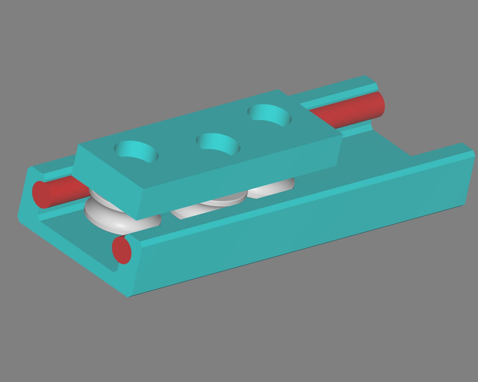
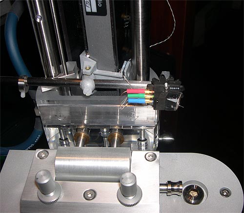
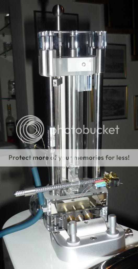
Speaking of triangle, here's a disassembled Souther arm that shows the triangular carriage with rollers on two quartz rails. I think having an extra roller complicates thing but at the same time it limits only to horizontal movement that allows manipulation of vertical bearing. It has plus and minus, no free lunch again.
Close up of the Souther successor, Clearaudio arm.
And here's quite a extensive collection of images of the arm.
http://www.aca.gr/forum/printview.php?t=1853&start=0
.
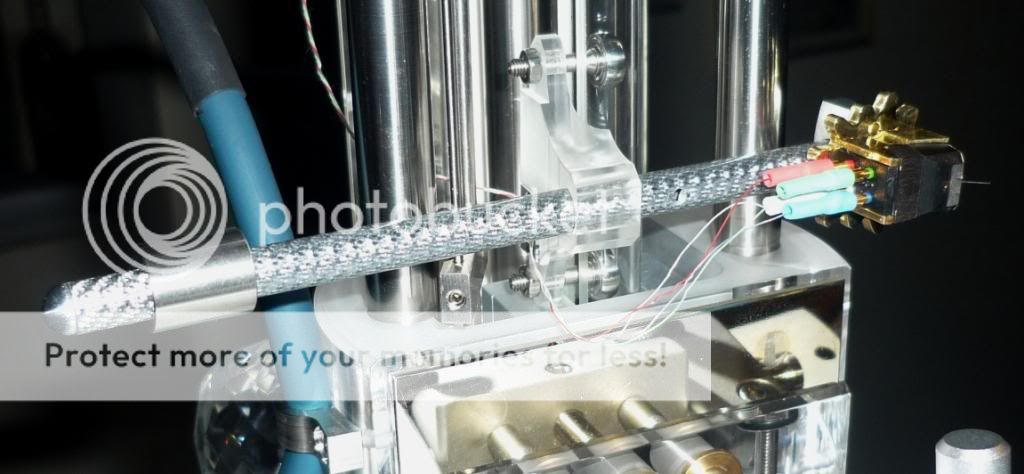
Clearaudio's answer to the Cantus. What's interesting is that the bearings are convex shape.


.
An externally hosted image should be here but it was not working when we last tested it.
An externally hosted image should be here but it was not working when we last tested it.
Close up of the Souther successor, Clearaudio arm.
And here's quite a extensive collection of images of the arm.
http://www.aca.gr/forum/printview.php?t=1853&start=0
.
Clearaudio's answer to the Cantus. What's interesting is that the bearings are convex shape.
.
Last edited:
- Home
- Source & Line
- Analogue Source
- Opus 3 Cantus parallel tracking arm