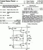
hi all. I'm new to this, but wanted to share my latest power amplifier project and solicit constructive comments and feedback.
my goals were to:
-design and build a fully symmetrical class A/B feedback amplifier with the simplest possible signal path.
-minimize the number of active components.
-still end up with a circuit that provides reasonable performance and sounds good.
-allow for easy upgrade to higher power output or??
Construction notes:
-D7 is mounted on one of the output transistors for thermal tracking.
-R33 is a trim pot for adjusting the output offset.
-The basic amplifier has +/- 50 volt supplies and puts out a little over 100 watts into 8 ohms.
-Optical isolator U1 controls the VAS idle current (about 10ma as drawn) allowing Q2 and Q4 to operate without emitter degeneration resistors.
-I've set the mosfet idle current to about 30-50 ma and I'm unable to detect any improvement by setting it higher.
Observations:
I've constructed the circuit as drawn and it seems to perform nicely. It sounds good to me and seems to be thermally stable with moderate heat sinking. I've also constructed a full two channel amp with two pairs of output mosfets and +/- 80 volt supplies. This amp also seems to work perfectly and the only other changes were increasing resistors R29 and 30 to 23k, and increasing the feedback resistors R4 and 31 to 4.1k.
I don't have the equipment to perform distortion testing, but it's quiet at idle and sounds good to me.
Has anyone seen a similar design using an optoisolater before?
comments welcome.
Thanks
Attachments
Nelson Pass uses such optoisolator. Maybe there is something similar in British Edge amps, but I’m not sure. BTW worth to try buffers with HEXFETs. These will reduces the anomalies of gate capacitance of FETs resulting decrease of odd harmonics with higher levels.
Attachments
I tried optronic isolation of the quiescent current installation for thermal trucks from Motorola
Last edited:
Thanks egra. Looks like the Pass circuit circuit is similar but only regulates current in the output stage, replacing a Vbe multiplier rather than controlling the VAS and input stages. I never managed to find that article when I was looking around.
In my first version I tried buffers between the VAS and mosfets, but I didn't really get significant improvement. then again my ability to measure performance is pretty limited.
I appreciate your feedback.
In my first version I tried buffers between the VAS and mosfets, but I didn't really get significant improvement. then again my ability to measure performance is pretty limited.
I appreciate your feedback.
