I'm building a stereo ACA, one chassis, two amp boards, one for each channel, with a linear power supply. I have a 300VA 2x20 toroidal transformer from Antek, and I'm planning to use a CRC filter. It seems to me that there are two options and I'm wondering if one is preferable to the other, what the pros and cons might be, or whether it makes any difference:
Option One: build a single power supply with one bridge rectifier and CRC filter, fed by the two secondaries in parallel, and feed both channels from this power supply.
Option Two: build two power supplies, each with a bridge rectifier + CRC filter, and feed one with one pair of secondary wires, feed the other with the other pair. One power supply would be for left channel, one for right. The two power supplies would be side by side on the same pcb.
It appears to me that option Two is used by the FirstWatt F1 amp, which has a single rail supply like the ACA. Other FirstWatt amps have one supply shared by both channels as in option One, but it isn't a good comparison because they have dual rail supplies, hence use two bridge rectifiers and two CRC filters, each fed by one pair of secondaries.
Also, some toroidal transformer manufacturers specify that the two pairs of secondaries are only to be used in series or parallel, and not independently, although Antek doesn't seem to give that warning. I read some posts about this issue, I guess it has to do with the amount of insulation separating the two secondary pairs, but I'm still unclear on just when that would be okay to do. Evidently it's not an issue for the F1.
Interesting dilemma 🙂
Going for dual mono construction has a lot going for it... that would be my first choice I think.
One thing to consider is that the ACA and its intended SMPS really function as a whole. The PSRR of the ACA is only average and that means any ripple on the rail will get passed through to the output and be audible as a buzz. The SMPS has no low frequency ripple in that sense. So you have your work cut out reducing any ripple to an acceptable value and C/R/C filtering might not get things as quiet as they could be.
That is something we could try simulating to get things in the right ballpark.
Interesting point you make about the insulation of the secondaries. Tbh its not something I've ever heard mentioned in normal use although you could envisage some scenarios where the circuitry each secondary supplies (not an ACA) could floated to be hundred of volts or more apart. I don't think its a concern here really.
Mooly, that's a good point about the ACA. I have all the components and I've built both amp boards, so I'll do some testing on the bench and try to measure the ripple, and see how quiet it is. I definitely don't want to end up with buzz or hum.
The issue with the secondary windings did not occur to me, since Antek doesn't mention anything. But I was looking at another manufacturer's website (Triad Magnetics) and I saw their note and that's what got me to wondering about that. You validated my understanding that it doesn't sound like an issue in this case.
The issue with the secondary windings did not occur to me, since Antek doesn't mention anything. But I was looking at another manufacturer's website (Triad Magnetics) and I saw their note and that's what got me to wondering about that. You validated my understanding that it doesn't sound like an issue in this case.
Recommend a variation on Option 2 – using CRCRC filters for each channel and a single 300VA transformer with 24V secondaries.
Start reading here: ACA amp with premium parts
Start reading here: ACA amp with premium parts
Please keep us posted on how things go. I am considering an ACA with a LT1084 regulated linear power supply.
I've just a tried a quick simulation of it and get confusing results.
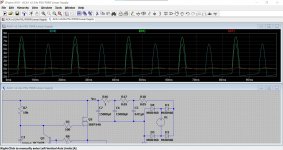
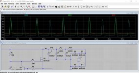
All other things being equal... and there is a massive difference in ripple depending which FET models are used for the outputs. I can't just see a reason why that is so.
Current draw is the same and the supply ripple the same.
First is the ripple at the speaker output using Bob Cordells models. Second using the LT supplied models and here the ripple is low.
Last image is the ripple voltage on the supply.
The .asc file uses default models and should click and run.
Attachments
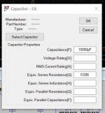
Here's an update: Mooly, I don't have LTspice but I've been curious to give it a try. I have the IRFP240 mosfets, I don't know what the IRFP240C is, a quick Google search of that didn't bring up anything. I put the thing together on the bench and made some measurements. I have a primitive testing set up - good multi-meter, okay signal generator, crummy old oscilloscope. I made two power supplies (side-by-side on one board), one for each channel. Each supply gets one of the secondary windings from the Antek toroidal transformer (300VA, 2x20) , NTE5313 bridge rectifier 200V 8A, one 2.2k bleeder resistor, CRC filter with C_1 = 15,000 uF Nichicon capacitor, R = 1 ohm, C_2 same as C_1.
I put an 8 ohm dummy load on each channel.
Left Channel: Vcc = 24.89V. V_BIAS = 12.01V, I_BIAS = 1.4A. The
Right Channel numbers are virtually identical.
My measurement of the power supply ripple is V_RIPPLE = 50mV.
I can't really measure the PSRR because the ripple on the amp output I gather is on the order of 10s of microvolts? My junkyard oscilloscope only goes down to
2 mV per division.
Putting a 1kHz sine wave into the input, it looks like it's just about to clip at:
Left channel: 7.28V into 8 ohms, Right channel 7.35V into 8ohms. So that's a little over 6.5 watts per channel.
I connected it to speakers - with no input it's dead quiet. My hearing is not so good, but my 25 old year old son has excellent hearing and I made him put his ear against the speaker, he couldn't hear anything.
I need to listen to more music with it. The highs were clear and nice - Joni Mitchell's voice sounds great. Bass seemed a little muddy. Maybe it's my speakers. I still need to figure out what speakers to go with, I understand the ACA is a little fussy with that. I have Klipsch KSB 2.1, which are 93dB sensitivity. I have a moderately large collection of AR and KLH vintage acoustic suspension speakers which are famously inefficient and which I assume will not sound good with the Pass's amps.
Tungsten, I have read some of that thread, there is so much information there! I guess the CRCRC filter with the 24V transformer would be better. I already overspent on my transformer budget because I initially bought a 200VA 2x18 and then decided it wasn't enough. So I've sunk $80 into transformers. Hopefully I'll get to use the 200VA for something one day.
The C version exists only in Spiceland 🙂 They are Bob Cordells own simulation models which have become to be highly regarded.
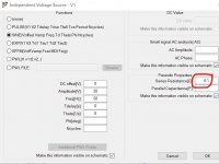
Two 15000uF caps is pretty big and so that will cut the ripple down considerably as will using 1 ohm between them.
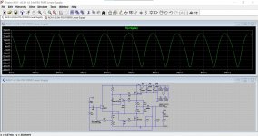
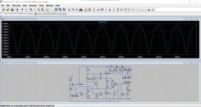
Just plugging those values into the simulation gives a ripple of... first image. Bias current on this sim is around 1.6A so that makes it slightly worse.
Output noise... second image. That is in the uV level but it seems unfeasibly low imo. I'm missing something I suspect.
Two 15000uF caps is pretty big and so that will cut the ripple down considerably as will using 1 ohm between them.
Just plugging those values into the simulation gives a ripple of... first image. Bias current on this sim is around 1.6A so that makes it slightly worse.
Output noise... second image. That is in the uV level but it seems unfeasibly low imo. I'm missing something I suspect.
Attachments
Maybe I'm a little late with this. I've posted before the power supply built for the ACA 1.6 that i did last summer. It uses one 500VA 30+30 Avel transformer- each secondary winding supplies its own channel. I did choke input and a LT338 regulator (works fine for a Class A current draw like this).
I don't believe using a single toroid will be a problem.
Ken
I don't believe using a single toroid will be a problem.
Ken
Attachments


I am also thinking of doing it but will likely use (again) 2x24ac secondaries with a regulated PS as per Zen 5 article (Figure 8).
https://www.firstwatt.com/pdf/art_zv5.pdf
CLC is an order of magnitude better than CRC (though the 2mH inductors are expensive especially in air core version).
https://www.firstwatt.com/pdf/art_zv5.pdf
CLC is an order of magnitude better than CRC (though the 2mH inductors are expensive especially in air core version).
Excuse my ignorance, but what is the advantage of air core chokes as compared to "transformer" type like a Hammond 159ZG (15mH, max. 4A, DC resistance 0.25R)?
Basically, Iron core inductors have a higher inductance for their size and weight, until the iron saturates.what is the advantage of air core chokes
Air core maintain their inductance unless they melt. 🙂
However, they are more expensive, larger and have a less contained magnetic field.
We are talking about power supply applications here.
Signal applications have additional trade-offs.
Thanks. Does this mean that the hysteresis of iron cores/non-linear behavior does not matter for power supply applications (assuming that the current stays below saturation)?
I'd prefer if my power supply did not approach the melting point of copper - or aluminum, for that matter.
I'd prefer if my power supply did not approach the melting point of copper - or aluminum, for that matter.
Yes.Does this mean that the hysteresis of iron cores/non-linear behavior does not matter for power supply applications
LOLI'd prefer if my power supply did not approach the melting point of copper - or aluminum,
My personal rule of thumb is to look at air core inductors for Class AB amps and Iron Core for Class A. Then sanity check with PDUD2.
Its all about Cost, weight, DCR, inductance, and Current saturation.
HTH
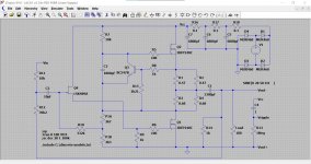
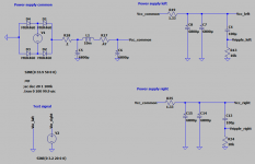
So, here is what I have come up with. No idea if this is even slightly realistic.
I started with Mooly's model from post #6 (many thanks for posting the .asc!).
I split off the power supply section, and copy-pasted the amp section to create left and right channels.
I increased the AC voltage to 33.9V, corresponding to a 24V transformer, because the series resistors (see below) eat up quite a lot of voltage.
I changed the RCRCRC filter to RC(L+R)C, then added separate RC branches for the left and right channel, in the hope that this would reduce cross talk.
For the choke, I used the parameters of the Hammond 159JZ: 10mH, dc R=0.160R, current rating 5A. I put a 0.6R resistor in series to adjust Vcc to 24V. This should also stop any ringing, but tbh I have no clue how to calculate or simulate that.
I set the resistor in each branch to 1.33R such that the voltage drop is about 2V - The resistors can then, in future experiments, be replaced by a LT1084 regulator and the resistors and cap that go with it. I doubled up the branch capacitor to get an RC time constant above 10ms, in the hope that this would efficiently cut out the 100Hz ripple and cross talk between the channels.
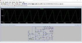
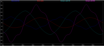
Finally, I put an 3.2V, 20 Hz AC signal into the right channel.
And that is pretty much it. I think the results look pretty promising (no surprise, given that I doubled the number of capacitors and added a big choke).
Cross-talk between channels and 100Hz hum seems to be in the microvolt range. Vcc ripple is less than 10mV peak-to-peak.

What is scary, however, is the current peak in C5, up to 12.5A. Diodes also peak at >15A.
I started with Mooly's model from post #6 (many thanks for posting the .asc!).
I split off the power supply section, and copy-pasted the amp section to create left and right channels.
I increased the AC voltage to 33.9V, corresponding to a 24V transformer, because the series resistors (see below) eat up quite a lot of voltage.
I changed the RCRCRC filter to RC(L+R)C, then added separate RC branches for the left and right channel, in the hope that this would reduce cross talk.
For the choke, I used the parameters of the Hammond 159JZ: 10mH, dc R=0.160R, current rating 5A. I put a 0.6R resistor in series to adjust Vcc to 24V. This should also stop any ringing, but tbh I have no clue how to calculate or simulate that.
I set the resistor in each branch to 1.33R such that the voltage drop is about 2V - The resistors can then, in future experiments, be replaced by a LT1084 regulator and the resistors and cap that go with it. I doubled up the branch capacitor to get an RC time constant above 10ms, in the hope that this would efficiently cut out the 100Hz ripple and cross talk between the channels.
Finally, I put an 3.2V, 20 Hz AC signal into the right channel.
And that is pretty much it. I think the results look pretty promising (no surprise, given that I doubled the number of capacitors and added a big choke).
Cross-talk between channels and 100Hz hum seems to be in the microvolt range. Vcc ripple is less than 10mV peak-to-peak.
What is scary, however, is the current peak in C5, up to 12.5A. Diodes also peak at >15A.
Pleased the .asc was useful.
Peak currents can be scary in simulation because of the lack of any resistance and (if not entered) no ESR for the caps. Add say 0.1 ohm into the AC transformer source and add something representative for the ESR. It makes quite a difference as here.
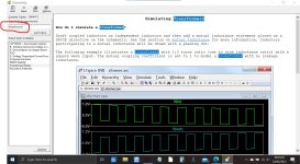
(Try attaching your images directly 🙂 its much easier and then they are here for keeps)
How to attach images to your posts.
Peak currents can be scary in simulation because of the lack of any resistance and (if not entered) no ESR for the caps. Add say 0.1 ohm into the AC transformer source and add something representative for the ESR. It makes quite a difference as here.
(Try attaching your images directly 🙂 its much easier and then they are here for keeps)
How to attach images to your posts.
Attachments
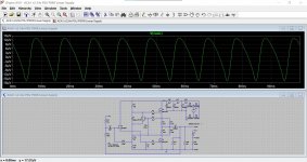
Adding a series resistance of 0.1R directly to the source decreases the peak currents by about 2A - my first resistance directly after the diodes was already 0.1R. For the capacitors, I used examples that come with LTSpice (Würth), in this case the series resistance is 37mR.
I have a suspicion (hope!) that there is some upstream impedance/saturation of the transformer that will keep the current to more reasonable levels. But I am new to this, so I really don't have much of a clue. I tried to include the transformer in the simulation, but without much luck.
PS: Thanks for the instructions on how to add in-line images. It does make like a lot easier. Note the different scaling factors for the voltages.
Attachments

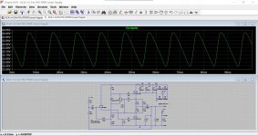
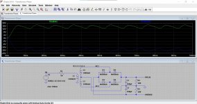
A real build will have more resistance from wiring, fuses PCB print and so on. It all adds up and reduces peak currents considerably. You might get an idea of the transformers output impedance/resistance simply by loading it with a known high current and seeing how much that pulls the voltage down.
Transformers are a bit of mystery to get right but this might get you started... The input is only 25 volts but it should all be tweakable.
Transformers are a bit of mystery to get right but this might get you started... The input is only 25 volts but it should all be tweakable.
Attachments

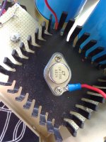
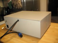
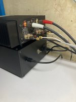
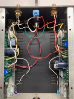
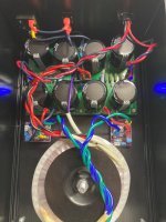
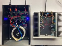
I built an external linear PSU for my ACA using a clone of a FirstWatt F1 single rail CRC power supply and an Antek AS-2218 (18V secondaries) that I had laying around. I used a cheap ebay chassis which required some drilling, which I'm not good at and don't enjoy. Unloaded the linear PSU gives 24.4V but loaded the ACA sees 21.7V, somewhat less than ideal, so the operatiing point was adjusted to 10.8V. The ACA's power switch is unused. Each channel sees it's own separate cap bank and rectifier for power, with a shared power ground and toroid core.
I get a lot of tight bass out of Noob Cube speakers driven by this amp, and not a lick of hum. This ACA drives these speakers with more gusto than my DIY Sony VFET does, running off a 36V brick. Happy New Year!
I get a lot of tight bass out of Noob Cube speakers driven by this amp, and not a lick of hum. This ACA drives these speakers with more gusto than my DIY Sony VFET does, running off a 36V brick. Happy New Year!
Attachments
- Home
- Amplifiers
- Pass Labs
- Options for Linear PSU for ACA