The Pass F5 wants 24V with 6A continuous and 10A peak.
Yes, I should be an engineer but I am not. I have been burrowing through these threads for a few days and have found options to take my 24V AC transformer and regulate the 34V DC (or so) it will become but all the devices I find are 2A at most. I looked on Digikey and Mousers. I have not found a DIY thread for high amperage PS, but reading the PS for DAC and Pre-Amps has given me a pretty good lay of the land. I don't fancy using resistors to drop the voltage either. Do I have to buy 18V transformers or is there a regulator that can manage more current?
Yes, I should be an engineer but I am not. I have been burrowing through these threads for a few days and have found options to take my 24V AC transformer and regulate the 34V DC (or so) it will become but all the devices I find are 2A at most. I looked on Digikey and Mousers. I have not found a DIY thread for high amperage PS, but reading the PS for DAC and Pre-Amps has given me a pretty good lay of the land. I don't fancy using resistors to drop the voltage either. Do I have to buy 18V transformers or is there a regulator that can manage more current?
No, you don't need to be an engineer. You just need to be able to learn. Asking for help means you are on your way. Good on you.
Take a look in the application notes for most 3 pin regulators and you'll find instructions for adding a larger transistor to increase the current capacity. It's really pretty simple.
A discrete regulator that I have built on breadboard several times can be found in here: http://www.passdiy.com/pdf/a75p2.pdf. Follow the same scheme as with a chip regulator to increase the current capacity using devices like MJL21193/21194 or MJL3281/1302 as boosters.
Practically, to pass that much current you'll need to parallel 3-4 high power devices. Use emitter/source resistors to help balance the current. You'll have ~32V after the rectifiers and maybe 30V after a CRC filter. Average dissipation will be around 36W per rail. Be sure to provide plenty of heat sinking.
A single channel F5 is biased to 1.3A.The Pass F5 wants 24V with 6A continuous and 10A peak.
A two channel F5 needs 2.6A continuous for it's output bias.
The peak requirement depends very much on the speakers and the music but could be up to 20Apk per channel.
Look up the PASS site for various regulated PSUs for his ClassA amplifiers.
While exploring these helpful options I found a discrete regulator that might be appropriate. The LM338 is rated at 5Amps.
LM338 - 5 Amp Adjustable Regulator
The ratings I listed of 6Amps continuous and 10Amps peak were found in the F5 manual but I may have quoted those numbers out of context and without understanding their significance.
1.3 Amps is a less intimidating number. And, my interests are in very efficient full range drivers in large horn cabinets. No disco array type speaker builds are foreseen in my future.
Is there any downside to using a simple device like this to regulate the voltage before it goes to the conventional unregulated capacitor PS of the F5 amplifier? Other than reducing the voltage does it introduce problems that a native 18v transformer would not pose to the passive capacitor power supply filter of the F5?
Would you be happy if your amp clipped anytime the total draw wanted to exceed 5A? That integrated regulator (all in once case, discrete is when you make it with a bunch of separate parts) has self protection current limiting.
Another engineering consideration is that the maximum current is limited by thermal considerations. From the data sheet, your maximum junction temperature is 125C. Drop it to 100C for reliability. Say your sinks are sized like Papa recommends, giving you 55C sinks. Now you are limited to a 45C rise from sink temperature to junction. What is the thermal resistance of the T package? 4C/W, so you are limited to 11W dissipation. But you need up to 60W. Time to boost it with a bigger pass transistor or 4.
High current regulators are tough beasts to tame.
Would you be happy if your amp clipped anytime the total draw wanted to exceed 5A? That integrated regulator (all in once case, discrete is when you make it with a bunch of separate parts) has self protection current limiting.
Another engineering consideration is that the maximum current is limited by thermal considerations. From the data sheet, your maximum junction temperature is 125C. Drop it to 100C for reliability. Say your sinks are sized like Papa recommends, giving you 55C sinks. Now you are limited to a 45C rise from sink temperature to junction. What is the thermal resistance of the T package? 4C/W, so you are limited to 11W dissipation. But you need up to 60W. Time to boost it with a bigger pass transistor or 4.
High current regulators are tough beasts to tame.
If you put say 20.000uF AFTER the reg, you can easily handle the peak requirements while the reg keeps the cap topped up.
jan didden
A single channel F5 is biased to 1.3A.
A two channel F5 needs 2.6A continuous for it's output bias.
The peak requirement depends very much on the speakers and the music but could be up to 20Apk per channel.
Look up the PASS site for various regulated PSUs for his ClassA amplifiers.
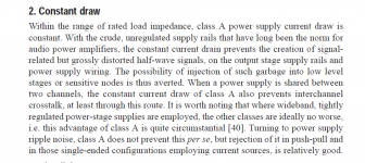
Now, that seems to be a contradiction: Classic definition of 'class A' states that it draws a (nearly) constant current. It draws continuous current which exceeds the maximum peak load (loudspeaker) current.
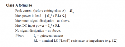
If it can draw up to 20A at peak output (some 18+A above its idle current), is it not then class AB?
In the past I have built up kit amps, following directions, like a big Hafler. It was custom to put a farad or two after the rectifiers and before the amp board. This was early 80's when voltages where going down and down for digital equipment and the surplus market was awash in huge high voltage capacitors. So this issue of having juice available for peaks was a non issue. Electrocution, days after it was powered down, was however a hazard.
But, because I have not figured out the dynamics of these voltage regulators it appears that putting them before a large capacitor confuses the the regulator. This can only mean I don't understand how they work and need to be pointed to a schematic which has the transformer-bridge-regulator ahead of the capacitors and is set up to work correctly reducing the voltage to the capacitors from 35VDC to 24VDC.
I have looked at the Zen 4 regulated PS and the Linsley Hood regulated PS for his Class A amp. I would understand if this were something that were too much to ask but if I had the correct values and components for my particular need to scrub about 10V from my transformer before the capacitors, that would be very much appreciated. Otherwise, the best advice has been to suck it up and just buy an 18v-18v transformer which are not at all hard to find and can be had for about $50.
generally no.Classic definition of 'class A' states that it draws a (nearly) constant current.
A ClassA amplifier uses all it's devices to actively control the output current all the time.
A push pull ClassA output stage transfers to ClassAB if the load demands more current than the ClassA limit.
A single ended ClassA output stage transfers to severe distortion if the load demands more current than the ClassA limit.
Both single ended and push pull ClassA do not draw nearly constant current when the load demands current. There is a single ended topology that does draw nearly constant current but it is so rarely adopted that it can be virtually neglected.
The second ref is also wrong.
Ben Duncan is usually a very reliable source. I don't know why he could have made those mistakes.
Ben Duncan is usually a very reliable source. I don't know why he could have made those mistakes.
The second ref is also wrong.
Ben Duncan is usually a very reliable source. I don't know why he could have made those mistakes.
Gee Andrew, I think I'm going to take HIS word for it. After all, he has all those letters after his name and you only have one after yours - 'T'
😀
Back to the topic:
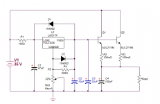
You want something like this:

2 or more pass transistors, depending on the load.
This can only mean I don't understand how they work and need to be pointed to a schematic which has the transformer-bridge-regulator ahead of the capacitors and is set up to work correctly reducing the voltage to the capacitors from 35VDC to 24VDC.
You want something like this:

2 or more pass transistors, depending on the load.
NOW THAT IS HELPFUL.
There are application sheets that I have been finding that show this circuit, but they presume one can derive the values.
It seems that there is much less for the capacitor bank of the F5 amp to have to smooth and that other than some cost of components and time that there would be no downside to having regulated DC going into the capacitors which become more of a cistern/reserve of power than a filter for ripple.
Is there some performance penalty for an amp like the F5 using regulated DC ahead of the "filter"capacitor?
I have had friends who found ginormous isolation transformers that they used to branch off the household electrical system and were dedicated to powering the audio equipment. This was a bit overboard but while it might be lost on the ear, I can remember the mutual grins and high fives after muscling a refrigerator sized transformer into the basement of a mate. I really miss those ham fests that sported military and industrial surplus.
Thanks again.
Bruce
looks simple and looks effective.
Compare this to Pass' Zener Follower regulated power supply.
The LM317 replaces the Zener. VERY similar but improved voltage with changing current demand.
MJL,
does the lm317 need to be the K version?
Could the T version with a 1.5A limit be sufficient?
If this circuit only sees the demand coming from a largish, bank of filter capacitors, that is, it sits on the other side of the circuit, does this pose a problem for an amplifier like the F5?
I know that this has been a concern for other types of amplifier circuits.
I know that this has been a concern for other types of amplifier circuits.
the regulated power supply sees both the capacitor bank and the F5 as it's load.
The F5//Caps is a complex impedance and the regulator must be capable of supplying that complex demand.
I would be very tempted to look at some type of current limiter to prevent the caps being charged too quickly. Electrolytics do not survive high V/us very well.
The F5//Caps is a complex impedance and the regulator must be capable of supplying that complex demand.
I would be very tempted to look at some type of current limiter to prevent the caps being charged too quickly. Electrolytics do not survive high V/us very well.
MJL,
does the lm317 need to be the K version?
Could the T version with a 1.5A limit be sufficient?
In this scheme, the LM317 only provides base current - all of the 'heavy lifting' is done by the pass transistors.
To produce the schematic, I just grabbed an LM317 from the list - it isn't important in regards to current capacity which type it is.
If this circuit only sees the demand coming from a largish, bank of filter capacitors, that is, it sits on the other side of the circuit, does this pose a problem for an amplifier like the F5?
I know that this has been a concern for other types of amplifier circuits.
I think I would split the total capacitance, putting half before the reg and half after.
- Status
- Not open for further replies.
- Home
- Amplifiers
- Power Supplies
- options for high amperage voltage regulation

