I'm building a power supply on the cheap for a GC amp (driving 4 ohm speakers), and after plenty of searching, I salvaged a functioning transformer from a 350 VA UPS battery backup unit. It has 2 sets of secondaries as measured by my multi-meter:
Red/White/Black: 16 volts from red to black, with the white as a center tap.
Blue/Brown: 20 volts across the 2 wires, no center tap.
Since both these are a bit low for an LM3886 chip, I was thinking of the following:
Red/White/Black: 16 volts from red to black, with the white as a center tap.
Blue/Brown: 20 volts across the 2 wires, no center tap.
Since both these are a bit low for an LM3886 chip, I was thinking of the following:
- Voltage doubler for the blue/brown wires, giving me 20(?) volts on +/- lines which is doable for 4 ohm speakers.
- Somehow try to wire the 2 sets together to achieve a higher voltage. This would give me about 18(?) volts on each line. I would think a voltage doubler at this point would put it at too high of power for a 4 ohm speaker load.
- Rewind the secondary. Probably the second "best" option behind just getting the right toroidal, but requires purchasing additional materials and I'd rather not if it can be avoided.
I don"t think a doubler would be a good idea as the current draw from the amp would be a bit much for the doubler , and you would need to use up to 3x times the capacitance in the PSU .....
The only thing I could suggest trying is putting the 20v tap and the 16v tap in series which would give you 36v ac which would be about 52v dc , then build the single supply version of the LM3886 that is in the data sheet ....
The only thing I could suggest trying is putting the 20v tap and the 16v tap in series which would give you 36v ac which would be about 52v dc , then build the single supply version of the LM3886 that is in the data sheet ....
For clarification: The voltages I posted were unloaded output. Don't you only multiply the voltage rating of the transformer by 1.4 to determine DC and not the measured peak output of the AC output?
For clarification: The voltages I posted were unloaded output. Don't you only multiply the voltage rating of the transformer by 1.4 to determine DC and not the measured peak output of the AC output?
Yes , 36 x 1.4=50.4v DC , my 52vdc was a guestimate ...
I was more asking: if you get a 18-0-18 transformer and plug it in, you'd get more like 20 some odd volts rectified to DC.
BUT: If you measure the AC off the transformer secondaries, would it read 18 or would it read the 20 some odd volts? Do you have to rectify it to read the higher voltages?
BUT: If you measure the AC off the transformer secondaries, would it read 18 or would it read the 20 some odd volts? Do you have to rectify it to read the higher voltages?
If those transformer secondary readings are RMS or average AC measurements, you should have 20V+ on both red/black & blue/brown pairs after rectification. The single supply version is a good idea, or an asymmetrical supply would probably work well enough too, AFAIK.
The question in your last post is more involved, as it includes different types of waveform measurements (peak, avg, RMS again), loaded or open circuit, etc. Generally speaking, the open circuit DMM measurement of a transformer secondary will always be higher than the voltage rating given the transformer. The given voltage rating of a secondary is always at a specific current rating.
The question in your last post is more involved, as it includes different types of waveform measurements (peak, avg, RMS again), loaded or open circuit, etc. Generally speaking, the open circuit DMM measurement of a transformer secondary will always be higher than the voltage rating given the transformer. The given voltage rating of a secondary is always at a specific current rating.
BUT: If you measure the AC off the transformer secondaries, would it read 18 or would it read the 20 some odd volts? Do you have to rectify it to read the higher voltages?
Im not sure I understand this question , but if you mean that to read 20 odd volts DC from your transformer , then Yes you would need to rectify the AC from your transformer into DC ..
A 18Vac transformer when fed with the rated mains voltage will measure 18*(1+regulation) using a Vac scale on a multimeter.
i.e. if the regulation is 7% (= 0.07) and you measure 18.9Vac then the rated secondary voltage is 18.9/(1+0.07) = 17.66Vac.
But that is less than 18Vac !!! Probably because the input voltage when you measured the 18.9Vac was different from the rated mains voltage.
If you have an 230:18Vac transformer, you will measure 18Vac when the mains input voltage is 230Vac and the secondary is loaded to deliver the rated current/VA. If either of these two conditions are not met accurately, then the secondary measurement will be wrong.
Red/White/Black: 16 volts from red to black, with the white as a center tap.
this is your main winding and if you notice even the pigtails would be heavy...
the other winding's are just auxiliary and is low current...
that 350 volt-ampere traffo is quite big for a gainclone...
even for two channels...
you can do a voltage doubler with it if you want to....
If you have an 230:18Vac transformer, you will measure 18Vac when the mains input voltage is 230Vac and the secondary is loaded to deliver the rated current/VA. If either of these two conditions are not met accurately, then the secondary measurement will be wrong.
The device it came out of was designed for US, so I'm assuming 110-120V would be the rated input. When I measured the "20 volt" lines it was just the transformer plugged into a standard US wall plug, and I set my meter to the AC mode and put the prongs on the meter to the leads off the secondary and read about 19.9VAC.
When rectified to DC, would this output (unloaded presumably?):
19.9VDC minus diode loss
OR
(19.9 x ~1.4)VDC minus diode loss?
this is your main winding and if you notice even the pigtails would be heavy...
the other winding's are just auxiliary and is low current...
that 350 volt-ampere traffo is quite big for a gainclone...
even for two channels...
you can do a voltage doubler with it if you want to....
I'll see if I can post a picture when I get home tonight, but as I remember the wires were about the same gauge. I understand that this doesn't necessarily mean they're the same current level level, however.
Any thoughts on capacitor sizing for the voltage doubler for a 2 channel gainclone into 4 ohm speakers? Trying to research it online seems to be all over the place with no concrete numbers except "a lot" with no frame of reference! When I put my circuit components into the spreadsheet that calculates power output for the chips, it came up to about 30 watts per channel.
I believe (though I might be wrong) that most doublers are Half wave rectified so you would need to use at least twice the capacitance you would use for a full wave rectifier to get similar performance , I would suggest 20,000uF a side for 2 channels.... there are also a couple different types of voltage doubler so use the one that gives a +/-DC supply as opposed to one that simply doubles the voltage ....
Like this one:
Google Image Result for http://www.stevencaton.com/Other%20Images/DC%20supply%20photos/DC%20Schematic.gif
Note that the B side of the transformer is your 0v or ground ..
Like this one:
Google Image Result for http://www.stevencaton.com/Other%20Images/DC%20supply%20photos/DC%20Schematic.gif
Note that the B side of the transformer is your 0v or ground ..
An externally hosted image should be here but it was not working when we last tested it.
this is a full wave doubler...
one last thing to check out, make sure those low voltage windings
are indeed isolated from the high voltage windings
and not auto transformer connected...
i have seen traffos out of UPS connected as such....
http://www.diyaudio.com/forums/power-supplies/238083-transformers-out-ups-systems.html
I started a thread about these, hoping I could use them for something.
Don't seem to be good for stereo anything.
I started a thread about these, hoping I could use them for something.
Don't seem to be good for stereo anything.
I'm building a power supply on the cheap for a GC amp (driving 4 ohm speakers), and after plenty of searching, I salvaged a functioning transformer from a 350 VA UPS battery backup unit. It has 2 sets of secondaries as measured by my multi-meter:
Red/White/Black: 16 volts from red to black, with the white as a center tap.
Blue/Brown: 20 volts across the 2 wires, no center tap.
Since both these are a bit low for an LM3886 chip, I was thinking of the following:
Any thoughts would be much appreciated! I'm thinking option number 1 is the way I'm leaning.
- Voltage doubler for the blue/brown wires, giving me 20(?) volts on +/- lines which is doable for 4 ohm speakers.
- Somehow try to wire the 2 sets together to achieve a higher voltage. This would give me about 18(?) volts on each line. I would think a voltage doubler at this point would put it at too high of power for a 4 ohm speaker load.
- Rewind the secondary. Probably the second "best" option behind just getting the right toroidal, but requires purchasing additional materials and I'd rather not if it can be avoided.
http://www.diyaudio.com/forums/power-supplies/238083-transformers-out-ups-systems.html
I started a thread about these, hoping I could use them for something.
Don't seem to be good for stereo anything.
you can still use them for gainclones...
with voltage doublers you can get rails of about +-22 volts..
good for chips that run on +-35 volt rails...
you can use that traffo if you want to...
lower rails give lower power to speakers, but if you
are not testing with sine waves for power and
just listening to music, that will do...
better than just tossing those traffos into the trash bin..
been there done that...
I believe (though I might be wrong) that most doublers are Half wave rectified
I'd say you're both correct.this is a full wave doubler...
The thing is, when the connection between the two caps is made the 0V reference for a bipolar supply, the result amounts to a half-wave rectified supply for each rail.
by definition, a full wave rectifier uses the full 360 degrees
of the sine wave, whereas, a half wave only 180 degrees...
said another way, the transformer supplies current
all the time, instead of half the time...
thus in a center tap rectifier, half of the winding
does not conduct current for the full 360 degrees
of the sine wave voltage...
enough of the theory, go ahead and build your amps... 😀
by definition, a full wave rectifier uses the full 360 degrees
of the sine wave, whereas, a half wave only 180 degrees...
said another way, the transformer supplies current
all the time, instead of half the time...
thus in a center tap rectifier, half of the winding
does not conduct current for the full 360 degrees
of the sine wave voltage...
enough of the theory, go ahead and build your amps... 😀
I saw 20,000uf was recommended earlier in the thread for each rail. With about 10,000uf on my filter caps, the music keeps playing for a second or 2 after power is cut until the caps drain. It surely would not take a full second to recharge the caps to necessitate such high capacitance?
Last edited:
ripple voltage is inversely proportional to capacitance...
but since the lm3886 has high psrr ratio,
such capacitance is big, but if you have them, use them....
otherwise 10000 ufd is what i will use...
but since the lm3886 has high psrr ratio,
such capacitance is big, but if you have them, use them....
otherwise 10000 ufd is what i will use...
I saw 20,000uf was recommended earlier in the thread for each rail. With about 10,000uf on my filter caps, the music keeps playing for a second or 2 after power is cut until the caps drain. It surely would not take a full second to recharge the caps to necessitate such high capacitance?
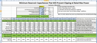
Once the rail voltages, speaker impedance, mains frequency, and the type of amplifier circuit are decided upon, he total capacitance per rail determines the rated max output power.
With more capacitance, the amp can play louder before it runs into the onset of clipping.
Also, with more capacitance there is a lower ripple voltage amplitude, which improves the sound quality, with how much improvement being dependent on the PSR (power supply rejection) characteristics of the amp.
If you have Excel, download the spreadsheet from the post at:
http://www.diyaudio.com/forums/power-supplies/240955-resevoir-capacitors-chip-amps.html#post3599692
If not, the formula is also posted there. Or, post your DC rail voltage and speaker impedance rating and I can post a snapshot of the results. The spreadsheet shows a range of capacitance values and the rated max output power for each one.
Attached is an example. In that example, boosting the capacitance from 10000 to 20000 per rail increases the rated max power from 56 Watts to 67.6 Watts, and going to 44000 uF would give you 75.5 Watts.
Attachments
- Status
- Not open for further replies.
- Home
- Amplifiers
- Power Supplies
- Options for getting the proper voltage