and chasing long-term perfect bias with just a Vbe multiplier is probably a prescription for futility and frustration.
Hi, Sam9,
Why do you say that? I saw in established commercial product, they do not use VBE multiplier for making bias. Some just use Diode-VR-Thermistor, some use stray of Diodes+VR, some use VBEmultiplier+VR in parrarel (where the adjustable is the parrarel VR, not the VBE multiplier).
Is this in principle says that VBE multiplier is not reliable for bias generator? Those people who makes the example above must have 10's of years of experience, and they decided not to rely on VBE multiplier.
Do you have any idea what makes the strange problem that I encounter (post#58)?
The key word is "perfect". I suspect that in the cases you mention, they came to a similar practical conclusion -- just get it close enough.
For years it has been remarked that what some one should do is put a tempco matched dioode in the package with the output device. Onsemi has a pre-production datasheet for just such a device, last I looked actual pieces were available as samples only on a limited basis. If they become available, I will be tempted to modify one of my EF amps to try them out.
Some non-EF topologies such as Sziklai pairs (especially with a pre-driver like one half the Quad 303) can do away with thermal tracking alltogether since the biased transistor runs very close to ambient. However, anyone who has spent much time making a Sziklai pair stable probably has another kind of experience with "frustration" and sometimes "futility".
😀 I encounter one now like in post #58.However, anyone who has spent much time making a Sziklai pair stable probably has another kind of experience with "frustration" and sometimes "futility".
All this time I use EF and the same VBE multiplier nothing happens. But this time, I use CFP, something strange happens.
hi heinrich,
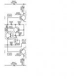
i noticed that your Vbe multipier's base feeds from the wiper arm(center) of the trimer, should something happen, such as corrosion in the field over time, you can lose your output tansistors!
better put that trimpot at the base emitter leg, at least shoud it become open circuit, minimal bias is applied to your output stage.

this must be the present and working amp pls. see attached file...
hi tony: yes you're correct I've used it by this time the one you said
failure may occur on the outputs if I do not do this as time goes by...
sorry I forgot to carry it on with the schemes....
rgds,
hienrich
Attachments
Hi,
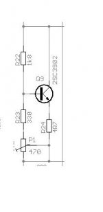
when determining currents in the Vbe multiplier I usually select the resistor string to run at about 10% to 15% of the total Vbe current.
Assuming that the transistor has a gain of 100 then the base current will be about 1% of the transistor current. Then the ratio of resistor current to base current will be about 10% / 0.9% = 11 so small changes in resistor current or base current will leave the voltage ratio along the string virtually unaffected. If transistor gain falls to 50 then the current ratio becomes 10% / 1.8% = 5.5 this is a bit low and would be the time to aim for resistor current towards the top end of the range i.e. 15% of total current, raising the current ratio to about 9.
So for a 10mA multiplier running with 1.3V at the output the resistors will total 870 R with the top resistor = 470R and the bottom resistor = 500r pot + 220r. Low hFE transistors would require resistors one E12 value lower (390r & 180r). These values are much lower than seen in many designs although similar to a few.
How will this affect Vbe stability?
Any comments?
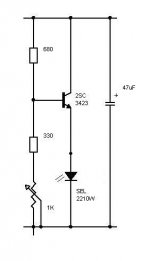
> What is you think about Vbe with zener.
The zener is merely protective - at the specified operating voltage (2 V) of the Vbe multiplier, the zener is pretty much completely open-circuit.
Actually, at 5.1V, I don't think it's of much use as a protective device either. Something like 3.3V or 3.9V is indicated.
The zener is merely protective - at the specified operating voltage (2 V) of the Vbe multiplier, the zener is pretty much completely open-circuit.
Actually, at 5.1V, I don't think it's of much use as a protective device either. Something like 3.3V or 3.9V is indicated.
Not sure about the impact - the 4R7 emitter degeneration resistor will increase the AC impedance of the base to about 1k, depending on the beta. It will also linearize the voltage-to-current transfer characteristics of the entire Vbe multiplier, making it look more like a like a small resistor rather than a (zener) diode.
I use th e Szizlaki - works very well. I doubt you need a 3rd stage though. I have a 0.1uF cap Collector to Base of the first transistor (which is the sensor). Emmiter to collector of th e pass transistor I use a good quality 10uF cap. some people would probably put a 1uF stacked foil here but to be honest I found no issues using an electrolytic.
This type of Vbe multiplier is especially good in designs where the VAS current is not fixed by a constant current source - you need a low impedance multiplier for this type of topology.
This type of Vbe multiplier is especially good in designs where the VAS current is not fixed by a constant current source - you need a low impedance multiplier for this type of topology.
- Status
- Not open for further replies.
- Home
- Amplifiers
- Solid State
- optimizing the VBE multiplier