Hi,
some time ago, I got some PA amplifiers for repair. The owner gave one of them to me as a present. That was a KMT 801. I rebuilt it completely and now I want to use it as a HiFi amplifier with plenty of headroom. Some modifications have been made so far:
-Improvement of the amplitude-frequency characteristic by changing the MFB-filter at the input OP
-changed VBE multiplier for stable idle current
-Replacement of the resistor for low fan speed by a capacitor and so on.
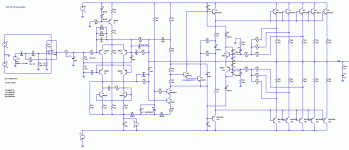
To understand the circuit better, I used LTSpice to simulate it. The Sanken Transistors have been replaced by Onsemi with similar ratings. The schematic is enclosed below. The simulation shows some drawbacks of the design:
-The THD exceeds 0,5% at some few kHz and about 250W power. By slight variation of C8, this could be reduced by factor 10, but I do not understand the cause for this effect in detail.
-V(B,E) of the SOA limiting transistors e.g. Q15 is getting negative in normal operating condition and the SOA limitation is not balanced well due to the asymmetric positive / negative impedance of the cascode voltage amplifier.
-I think it might help to enhance the open-loop bandwidth of the circuit, but I have not understood the function of the differential amplifier Q1...Q6 well enough to do this.
Could someone give me some hints, please?
