Hi Guys
Threw the new and improved Hans/Ralph two phase motor controller on the turntable. The new generator does the frequency change at .01 hertz intervals. That shows up as .005 change in rpm. Now for the even better news this gen is the most stable thing that has ever been put in front of the turntable. The rpm guage would only drift .002 rpm through the hole album. The big Hurst motor still makes noise but I have it isolated pretty well.
All I can say is it sounds stable and great. New motor should be here today we will see how a more sophisticated motor run on 3 phases will do??? The Hans 3 phase splitter is already done.
Is this the best thread by far on the subject or what. There are block diagrams, schematics, and various ways to get to the goal. And of course finished products that work. I know I appreciate all the help I have received. One step closer to Audio Nirvana!!!
Thanks
Tom
Glad to hear it Tom, congratulations, and thanks for sharing all the info. I can't wait to start on my 3 phase VFD for my Papst motors. Just a few more days now, I'm really chomping on the bit.
My plan is to use this 2 channel generator: Digital Signal Function Generator Arbitrary Waveform Meter 250MSA s 24MHz A9E9 | eBay . The reason for this generator is that the .01hz accuracy should be more than enough. If I have my math right, that would be a theoretical .3rpm at 1800 rpm, it ships from the USA, so also saves some time. The 10V adjustable DC off set should be enough, it has memory recall, 0 memory is a start default, and it has a 12 bit wave form. Admittedly, I really don't know if a 12 bit wave is important or not, but doubt it'd hurt.
That will feed Han's post # 238 splitter, which will feed 3 class D 100 watt amps, which will feed 1.5 ohm ballast resistor, and some nice little 15:230V R core 30Va transformers (with screens between primary and secondary). All that will be powered by a 24V 8.3A switching power supply.
I'll build a shielded box with fans for the VFD, and install BNC connectors in the box to connect the generator via cables. That way I can detach the generator if I want to use it in the shop for other purposes.
twystd
I have been following this thread for some time, thanks to all so far.
I have not seen much discussion of motors, I would like to use the three phase solution.
Does anyone have info on motor manufacturers or sources?
I have an old VPI scout with the original hurst motor, making mounting or machining new pulleys is not a concern.
I don't know of anyone currently manufacturing suitable 3 phase motors. The best source I know of is the Papst motors out of old Rek-O-Kut turntables, on ebay. Sometimes you can pick up an old junker with a working motor, at a reasonable price. I've got 2 old TTs with working motors shipped for ~ $100, but they are hard to find at a reasonable price. Some of these greedy idiots on ebay, find an old ROK TT in Grandpa's attic, and think they've struck "vintage" gold.
Know what you are looking for, they put several motors in the old ROKs, some of them not so great, such as the notorious "Borg death cube" motor. If you get real lucky, you might find one of the huge Ashland motors that were put on transcription TTs. The Ashland motor really is a case of overkill, as the Papst motor when run on 3 phase, is more than powerful enough to drive the heaviest platters.
twystd
Wow... just found this amazing thread and will need to go back and study all of it. It hits close to home as I am using a VPI HW19 MkII with a MkIII motor in it, powered with a fairly simple power supply (XR2206 sine generator > 100W amp > Avel Lindberg toroid to step up to 115VAC. I've been using this for a few decades now and it works great, and there is a significant sonic improvement over just line voltage (mainly in the pitch and extension of the bass). But I've never thought about powering the motor with multiple phases, and power is really cheap these days with Class D amps so readily available.
I have a phoenix road runner. It has a digital display that reads out 3 places after decimal point. So the perfect read on this readout looks like 33.333.
Enjoy the ride
Tom
Enjoy the ride
Tom
It looks as if everyone has their preferred source for generating the sinewaves, but I was wondering if there would be any interest in a DIY version?
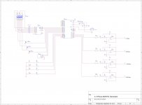
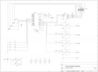
Using an Atmel AT89C51RB2, which has a 5 channel 8 bit PWM built in, I was able to generate 50-90 Hz sinewaves with 0.05 Hz resolution, crystal accuracy, <1% distortion and output zero, 90, 120 & 240 degree offsets simultaneously (adjustable in ~1.4 deg steps) with only a few additional components (hex inverter, quad op-amp, EEPROM, 3 digit LED display). Including PCB, BOM cost is probably ~$35. It would require soldering (thru-hole or SMT). I have no interest in selling parts or PCBs, but I can provide a .hex file that can be downloaded into the micro and gerber files that can be used to fabricate PCBs at your favorite board house. Any thoughts?
Using an Atmel AT89C51RB2, which has a 5 channel 8 bit PWM built in, I was able to generate 50-90 Hz sinewaves with 0.05 Hz resolution, crystal accuracy, <1% distortion and output zero, 90, 120 & 240 degree offsets simultaneously (adjustable in ~1.4 deg steps) with only a few additional components (hex inverter, quad op-amp, EEPROM, 3 digit LED display). Including PCB, BOM cost is probably ~$35. It would require soldering (thru-hole or SMT). I have no interest in selling parts or PCBs, but I can provide a .hex file that can be downloaded into the micro and gerber files that can be used to fabricate PCBs at your favorite board house. Any thoughts?
Attachments
I have a phoenix road runner. It has a digital display that reads out 3 places after decimal point. So the perfect read on this readout looks like 33.333.
Enjoy the ride
Tom
You are the lucky one...🙂. It's a bit punchy $-wise for speed measurements. Is any other $-dissent way to measure speed beside strobing light? I use iPhone soft called RPM, but it is also not that stable. My numbers are very jumpy and hard to get to the mean. StDev is quite high.
Sent from my iPhone using Tapatalk
Pyramid, very nice of you to offer this. I am very interested, but have never had a PC board made before. If someone could point me in the right direction, I could probably pull it off. If someone else more knowledgeable wants to do this fine, and I'd help with the costs. Just for grins, I started to look around, and found a US based company that offered online quotes. The minimum run was 5, and was based on size. I took a wild guess at 3" x 4", and another for 4" x 6". I have no idea what size would actually be needed, but thought that might give me some idea. There was just about a $5 difference in the size. I also got a price for 10 boards as well. The prices ranged from $125 for 5, and $180 for ten for a 3" x 4", and $130 for 5 and $185 for 10 in the 4" x 6" size. This was for a 2 layered board .062" thick, their best quality board.
twystd
twystd
Hi Pyramid.
I'm also very interested in your wonderful offer. I'd love a diy option from a respected designer as opposed to the sketchy stuff from eBay.
twystd, I'm in for 5 boards if it helps to reach a minimum, although I'm sure others will want some too.
I'm also very interested in your wonderful offer. I'd love a diy option from a respected designer as opposed to the sketchy stuff from eBay.
twystd, I'm in for 5 boards if it helps to reach a minimum, although I'm sure others will want some too.
Hi Pyramid,
First of all my compliments with your fantastic achievement.`
I am also interested, even willing to make the Gerbers but not in the production of the PCB's.
But I have a few suggestions:
a second order 200Hz filter is a bit meager for suppressing harmonics from a square wave, and the amplitude of the squarewave largely depends on the power supply.
Linn is using a 6th order 100Hz LPF , and it would hardly effect costs.
Last but not least, it would bring quite some extra comfort when it would be possible to adjust the amplitude of the various sinewaves.
And could some extra hardware be added to the PCB to load the hex file and also to make it possible to load future updates.
Maybe this programming can be performed with a USBTINYISP ?
Just a few thoughts.
Regards,
Hans
I feel 1% THD from the oscillator is slightly below par. Download this program to add as many orders of filters as you like. You can do approximations of distortion from data offered. Chebishev is usable as it is a fixed frequency. I gave a figure of - 45 dB as a target figure. If using a transformer output these tend to be about - 54 dB if of good quality. - 60 db seems about right for the oscillator. TL074 ( 84 ) is OK as an op amp. Being JFET is sometimes is easier to use.
Download FilterPro – Texas instrument free filter calculator | Xtronic
Download FilterPro – Texas instrument free filter calculator | Xtronic
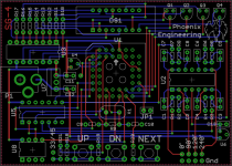
twstd- I just sent the files to OshPark.com for PCB fabrication of prototypes. 3 pcs are $46.80 or $14.60 each. If the PCB checks out, I can "share" the design where all you have to do is go to their site and click on buy, no file transfers needed. Only restriction is you have to buy 3 pcs at a time (or multiples of 3) and the boards are purple. If someone wanted to do a group buy, I have a board house that could do quantities at a bigger discount. I also created a shopping cart on Mouser that can be shared so all someone has to do is go to their website and enter an access code to pull up a complete parts kit. Cost is $33 for 1 pc qty. As with the PCBs, a group buy would decrease the cost. FYI, the PCB is 3.5" x 2.5". I did the PCB layout with all through-hole parts as SMT can be challenging for some people to solder, especially if they don't have the right equipment. Alot of the SMT parts are going fine pitch (0.0125" pin spacing) or leadless which requires a hot air station to solder.
Hans-The PWM clock is running at 14.4kHz so a 2nd order BW filter will attenuate the square waves by -72dB. If more is needed, you could certainly add passive filters between the generator and the amps. I could add a serial interface to program the chip in-circuit, but it adds cost, size, complexity and you still have to construct a programming cable and use Atmel's software. It can be done, but I prefer not to. If a group buy is done, I could program the chips or someone with a universal programmer could do likewise.
Nigel-The output of the breadboard version was ~0.8% distortion, but it didn't have the hex inverters driving the filters (8051 ports are not designed to drive complex loads and this is causing most of the distortion). It will be interesting to see what the prototype PCB measures. The Eagle PSU generator portion has ~0.015% distortion, but the output of the transformer (115VAC) is closer to 0.5%, probably due to core hysteresis in the xfmr. I've never seen a commercial PSU using a xfmr output deliver less than 0.5% THD. I don't think additional filtering will have much effect on the final result.
Attachments
Last edited:
Count me in. I have a usbasp programmer, but i think it can only be used in-circuit.
Just let me know how I can help out.
Just let me know how I can help out.
Last edited:
I have more oscillators for this project than I know what to do with, but I would very definitely be interested in this 'bespoke' version.
The only caveat I can come up with is for someone to source a pre-programmed uController chip.
The only caveat I can come up with is for someone to source a pre-programmed uController chip.
Distortion seems fine. I can only speak of motors I know of and suspect many will be similar. - 46 dB minimum seems a good standard. A power valve in triode might do this and would seem suitable even without feedback. I noted a very similar debate about very big motors and meeting regulations. The motor measured at various places from power input to consumer unit showed very different results even on a fat piece of wire. The correction circuitry added at the motor can be checked at the consumer unit to prove the real advantages if they exist. Sometimes it can be worse!
People reading this will adapt these ideas to their needs. I suspect many will not have a VPi. 4 phases could be engineered. Of more value might be to use 2 x 2 phase motors with a slight rotational speed difference between them. This might just take up belt slack. If the motor vibration is minimal I suspect the so called dynamic wow would be reduced with a taught belt. Top quality turntables look more like tape decks on analysis of wow and flutter. Drive train being the reason.
People reading this will adapt these ideas to their needs. I suspect many will not have a VPi. 4 phases could be engineered. Of more value might be to use 2 x 2 phase motors with a slight rotational speed difference between them. This might just take up belt slack. If the motor vibration is minimal I suspect the so called dynamic wow would be reduced with a taught belt. Top quality turntables look more like tape decks on analysis of wow and flutter. Drive train being the reason.
- Home
- Source & Line
- Analogue Source
- Optimally driving a (VPI) synchronous turntable motor