It would be easier to check if you'd drop the title or ISBN... Bezos' Bookstore returns one result for Walt Jung (and plenty for a certain Carl Jung, but I don't think his psychoanalytic methods are particularly helpful here): Op Amp Applications Handbook. ISBN-13: 978-0750678445. Free download from ADI here: https://www.analog.com/en/education/education-library/op-amp-applications-handbook.html It is indeed a good book. Is this the one you were thinking of or is there another?A very long time ago when 5532 was about as good as they made, Walt Jung wrote a book about using op-amps for audio. Y-all should have a copy?
The inverting amp also has lower loop gain than the non-inverting amp. 6 dB lower at unity gain. How that ends up affecting the performance of the circuit should be evaluated too.1. An inverting amp avoids input CMRR distortion because the inputs are fixed at ~ground voltage. However, an inverting amp is slightly noisier than a non-inverting amp, and the input impedance is relatively limited.
Tom
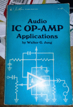
The version I have looks like this :
https://i.ebayimg.com/images/g/ddQAAOSwmCphsoct/s-l500.jpg
but it looks like there is a newer version.
https://www.amazon.com/Audio-Op-Amp-Applications-Walter-Jung/dp/0672224526
The ADI link is something else and doesn't seem to focus on the op-amp itself as much as Walt's original book. Walt wrote about the internal design of op-amps and the resulting performance. For example, he points out that the JFET amps like LF356 use a P-channel based quasi output that has a distinct output distortion characteristic, while low power op-amps like LM324 have a class-C output that is very poor choice for audio. And generally, low power op-amps have poor slew rates, again making them a poor choice for audio. In those days the internal design of most op-amps was public, and we could predict the audio performance, but today vendors are not as inclined to share their secrets. Walt tested the various parts of op-amps with circuits that revealed input, output and other internal mechanisms, and compared different op-amps with plots.
Today's op-amps have mostly overcome the problems of those old op-amps, but without internal design information, it is easy for the spec's to simply not mention serious issues, although perhaps only experienced designers recognize common issues and features from the schematic. Likewise, many op-amp spice models use theoretical components like current or voltage sources that are impossible in reality. The results are such things as output that exceed the power supply input and supply pin current that does not reflect the load. I have never seen a LTC spice model with such problems but public 5532 and TL071 spice models often do. There are/were known problems with LM3886 spiced models and TL2071 spice models.
Usually "infiniteit seems that the lowest THD is achieved when R load is 2k.
Once upon a time we used vacuum tube opamps, and 100k load was a typical rating. (100V at 1mA)There is nothing magically or optimum about 2k load
Transistors could not run such voltage but would pass large current. 10V at 5mA, 2k, seems to have been a popular spec-point.
Of course most general-purpose chips will do 12+V and 24+mA kinda-clean; '5532 will do that pretty clean.
I am wondering if there are certain parameters that will make popular opamps like NE5532, LM4562, TL072, OPA2134, and others, to give the best performance as far as THD and sound quality?
One factor perhaps worth avoiding could be inadvertent RFI ingress. Might take some extra care in certain applications such as dac I/V and or differential summing stages. https://cherryclough.com/media/file...or RF immunity, EMCJ, Issue 84, Sept 2009.pdf
https://www.ti.com/lit/an/sboa128a/sboa128a.pdf?ts=1657615596482
https://www.maximintegrated.com/en/design/technical-documents/app-notes/3/3950.html
I think a supply rail voltage of +/-15vDC is adequate for most DIY purpose but for line level use it is recommended to use +/-17vDC. Btw for 5532 Douglas self recommends 0.1uf between the rails to deal with spurious oscillation.
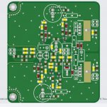
JLCPCB does 4 layer now, and it costs 8 USD versus 2 USD for 2 layers.
For opamps, the natural stackup is Signal, Ground, -15V, +15V. That saves a lot of time on the layout, because routing those damn +/-15V traces everywhere sure is annoying.
Ground plane on layer 2 makes EMI filters effective.
In addition you get low power supply inductance, which allows spraying 100nF caps at regular intervals without any issue with ringing. I put them in pairs, positive and negative caps end to end with ground vias in the middle, which solves the problem of class B currents leaking into ground.
The nice thing about planes is the inductance is per square. So a 10mmx10mm plane has roughly the same inductance as a 100x100mm one, and it's a tiny inductance In fact it is less than the inductance of the trace between the opamp and the decoupling cap next to it if traces are used instead of planes.
If the board only has linear circuits (like no precision rectifier, no vu-meters etc) and all the opamp circuits only touch ground through the decoupling caps and feedback networks, resistor dividers etc... and if the connectors are placed correctly (all on the same side) then the only current through ground should thus be linear with signal, keeping it clean...
Then aplication of the G-word...
I have a strong intuition that a large part of the hundreds of pages of topics detailing the wide sonic differences between opamps have a... relationship... with 50MHz opamps being put on on sockets, or as retrofit on boards with decoupling barely suitable for a 3MHz opamp, etc 🤣
I'm not saying it's all woo-woo, I mean RC4558 needs to die. But when I stick the scope probes into a 2-layer board DAC without ground plane, and the power supplies have enough fur on them to make a carpet, well...
Last edited:
To this day the worst of the worst was Hifimediy ES9023 because no ground plane, and the optical SPDIF output LED shared the ground trace with the audio out connector, so you could see the SPDIF signal in the audio output. But it has no opamps, so it's not participating in this topic. Therefore I nominate as worst board with opamps ever, the 8 channel DAC in Onkyo TX-NR 905. With extra fail points for bragging about "top of the line flagship PCM1796" while being a waste of good chips.

2 layer, no ground plane, noise everywhere, split grounds, where is the digital ground anyway, and it is sandwiched with the DSP board which also has no ground plane and bathes it in EMI from above.

It is a good example of what not to do with opamps. Worthy of study. There is not a single point on this board where you can stick a probe and not get a screenfull of fuzz on the scope.
Oh yeah they also thought the best place to put the phono preamp is on top of the DSP board.
2 layer, no ground plane, noise everywhere, split grounds, where is the digital ground anyway, and it is sandwiched with the DSP board which also has no ground plane and bathes it in EMI from above.
It is a good example of what not to do with opamps. Worthy of study. There is not a single point on this board where you can stick a probe and not get a screenfull of fuzz on the scope.
Oh yeah they also thought the best place to put the phono preamp is on top of the DSP board.
Last edited:
Brilliant! Let's put a low-noise preamp with 40-60 dB of gain right on top of a digital bounce house. Yay!Oh yeah they also thought the best place to put the phono preamp is on top of the DSP board.
Appreciate it. Thanks. Judging the book by its cover, it looks like it's from the era of the uA741, LM324, etc.The version I have looks like this :
https://i.ebayimg.com/images/g/ddQAAOSwmCphsoct/s-l500.jpg
but it looks like there is a newer version.
https://www.amazon.com/Audio-Op-Amp-Applications-Walter-Jung/dp/0672224526
Yes and no. The schematics were often simplified and would still require some design work to copy the design. But I agree that they did show the topology in much more detail than they do today. Funny how that is. If a company spends $1M developing a state of the art opamp they don't give the design away for free.In those days the internal design of most op-amps was public, and we could predict the audio performance, but today vendors are not as inclined to share their secrets.
If there were serious issues they'd show up in the performance plots. Also, manufacturers give away samples so you can test drive the products in your application circuit. That's the real test.Today's op-amps have mostly overcome the problems of those old op-amps, but without internal design information, it is easy for the spec's to simply not mention serious issues, although perhaps only experienced designers recognize common issues and features from the schematic.
Sure. They're often behavioural models. I'm not sure you realize what you're asking for here. Even if the manufacturers were willing to let go of their schematics and their semiconductor models (even if in encrypted form) so that you could get a device-based model, it would be an absolute nightmare to use. It wouldn't take many opamps in one circuit before SPICE would barf and not converge on a DC operating point solution. Also keep in mind that we have different expectations of opamps these days than we did in the 1970s. For example rail-to-rail I/O is pretty much a given these days except for a few applications. That complicates the designs too.Likewise, many op-amp spice models use theoretical components like current or voltage sources that are impossible in reality. The results are such things as output that exceed the power supply input and supply pin current that does not reflect the load. I have never seen a LTC spice model with such problems but public 5532 and TL071 spice models often do. There are/were known problems with LM3886 spiced models and TL2071 spice models.
My point is: Don't dismiss a modern part simply because the manufacturer won't show you the schematic. There have been dramatic improvements in the semiconductor industry over the past few decades and it would be a bit silly to not take advantage of those improvements.
Also note that a current production NE5532 is unlikely to be the same IC as an NE5532 bought when it first came out. The older manufacturing equipment has long been scrapped and the product has been redesigned in a newer semiconductor process. The process of redesigning an IC can be pretty challenging, actually. Not only does the new design have to meet the old specs, it also has to replicate the various quirks and oddities of the old design. That can be fun.... 🙂
Tom
First edition of Jung's Audio IC Op-Amp Applications (Extracted from IC Op-Amp CookBook), 2nd printing, is 1976.Appreciate it. Thanks. Judging the book by its cover, it looks like it's from the era of the uA741, LM324, etc.

2nd edition is marked late 1980s.
I would have to un-bury my Cookbook to see if it is all in there, or if the Audio IC book has "more".
I believe it pre-dates the LM324.
It covers 101 Family, 709 Family, 741 Family, and special-purpose uA725, LM108, MC1556 and 4556, hi-volt MC1536, 8007, LM110, AC and hi-level types 8007, LM110, SE531, LM118, HA-2620, uA715, and SE540. An example includes a '3080.
You see it is very much Of Its Time.
There is rather a lot of examples based on '709, because, for all its many faults, the '709 was not truly bettered for audio purposes for many years. I gave up on 709 because compensation needed thinking and tiny caps, and because a short would kill a 709 quick, and because '301 was easier to compensate and much harder to kill.
Last edited:
The genesis of the LM324 is in a 1972 paper.1976. ..... I believe it pre-dates the LM324.
Op Amp History
pages H.49 and H.67
Wikipedia says "released 1972", without reference.
I discovered how to simulate distortion using TINA TI 🤓
Just for fun simulated few opamps in inverting vs non-inverting configuration. Gain was set to 2.2. Load was set to 2K.
Note - ignore the load rating.
frequency - 1KHz
THD:
lm4562, 2.25ms - 0.000005912%, load - 0.0000970%
lm4562inv, 1.7m - 0.00000757%, load - 0.0000969%
ne5532, 2.25m - 0.0000219%, load - 0.0000948%
ne5532inv, 1.75m - 0.00000640%, load - 0.0000961%
opa2134, 2.25m - 0.0010873%, load - 0.0011071%
opa2134inv, 1.75m - 0.0000060329%, load - 0.0000965%
opa1652, 2.25ms - 0.00012874%, load - 0.00021373%
opa1652inv, 1.75ms - 0.00001055, load - 0.00012011%
opa1656, 2.25m - 0.00659%, load - 0.0065704%
opa1656inv, 1.75m - 0.000006446%, load - 0.000096617%
opa1612, 2.25ms - 0.0000073535%, load - 0.000096458%
opa1612inv, 1.75ms - 0.0000060104%, load - 0.000098847%
Based on those results I have come up with two lists:
Opamps that are best to use in non-inverting configuration: OPA1612, LM4562
Opamps lowest on THD in inverting configuration:
OPA1656 (0.006583554 better),
OPA2134 (0.0010812671 better),
OPA1652 (0.00011819 better),
NE5532 (0.0000155 better).
Opamps that are good enough for both: LM4562, OPA1612, NE5532
Last edited:
I wonder if the quoted "2k" resistor is intended to be the feedback resistance to negative input, or "load" resistance to ground (or the input impedance of the next stage), or those two in parallel. Regardless, in general higher resistance (aka "lower load" - lower output current from the opamp) makes for lower distortion, but noise increases in proportion to increasing resistance. 2k is probably inaudible, but going up one or two orders of magnitude is probably not. It's an engineering trade-off, just like so many other things.
Regarding TINA TI or the Linear Technology/now Analog Devices equivalent LTspice or other simulators, I don't know how much I would trust a simulation for these "measurements." For one thing, I've read the manufacturers have much better in-house-only chip simulation files than the ones they release to the public. Also, often the datasheet schematics are "representational" and not the complete schematic, so a simulation based on them would likely not be "correct." I recall that Samuel Groner has published op-amp distortion measurements, it would be interesting to compare with simulations.
Regarding TINA TI or the Linear Technology/now Analog Devices equivalent LTspice or other simulators, I don't know how much I would trust a simulation for these "measurements." For one thing, I've read the manufacturers have much better in-house-only chip simulation files than the ones they release to the public. Also, often the datasheet schematics are "representational" and not the complete schematic, so a simulation based on them would likely not be "correct." I recall that Samuel Groner has published op-amp distortion measurements, it would be interesting to compare with simulations.
opa1656, 2.25m - 0.00659%, load - 0.0065704%
Looks uncharacteristically poor. What was the source impedance?
As these were simulations, I presume a voltage source with exactly zero ohms. Seeing the schematic, resistor values and source voltage level (specified as RMS, Peak, or P-P) used in each case would also be helpful.Looks uncharacteristically poor. What was the source impedance?
Must be something wrong with the model then as the DS shows OPA1656 distortion below -120dB in that config.
Whats the mechanism behind such ringing with the 1nf caps? I recently did a discrete opamp layout and did end up spraying the decouplers everywhere thinking it was a good idea. They are at every power trace entry point at constant current sources and the output bjt source pin.JLCPCB does 4 layer now, and it costs 8 USD versus 2 USD for 2 layers.
For opamps, the natural stackup is Signal, Ground, -15V, +15V. That saves a lot of time on the layout, because routing those damn +/-15V traces everywhere sure is annoying.
Ground plane on layer 2 makes EMI filters effective.
In addition you get low power supply inductance, which allows spraying 100nF caps at regular intervals without any issue with ringing. I put them in pairs, positive and negative caps end to end with ground vias in the middle, which solves the problem of class B currents leaking into ground.
The nice thing about planes is the inductance is per square. So a 10mmx10mm plane has roughly the same inductance as a 100x100mm one, and it's a tiny inductance In fact it is less than the inductance of the trace between the opamp and the decoupling cap next to it if traces are used instead of planes.
If the board only has linear circuits (like no precision rectifier, no vu-meters etc) and all the opamp circuits only touch ground through the decoupling caps and feedback networks, resistor dividers etc... and if the connectors are placed correctly (all on the same side) then the only current through ground should thus be linear with signal, keeping it clean...
Then aplication of the G-word...
I have a strong intuition that a large part of the hundreds of pages of topics detailing the wide sonic differences between opamps have a... relationship... with 50MHz opamps being put on on sockets, or as retrofit on boards with decoupling barely suitable for a 3MHz opamp, etc 🤣
I'm not saying it's all woo-woo, I mean RC4558 needs to die. But when I stick the scope probes into a 2-layer board DAC without ground plane, and the power supplies have enough fur on them to make a carpet, well...
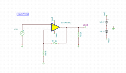
Ok, I did separate schematics for non-inverting amplifier.

Here are the conditions:
Non-inverted amp
Frequency = 1KHz
Input voltage = 2Vrms
Gain = 3, Feedback resistor = 2K, Ground resistor = 1K
Load = 2K
Time measurment = 2.25mS, at peak voltage of 8.43V
And results:
OPA2134 - 0.00671%
NE5532 -- 0.000129%
LM4562 -- 0.00000703%
OPA1612 - 0.00000956%
OPA1656 - 0.00000657%
OPA1652 - 0.0002008%
Attached zipped TINA TI sim files for all opamps.
Attachments
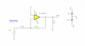
Here are results for inverting amp:

Inverting amp
Frequency = 1KHz
Input voltage = 2Vrms
Gain = 3, Feedback resistor = 3K, Input resistor = 1K
Load = 2K
Time measurment = 1.75mS, at peak voltage of 8.43V
OPA2134 - 0.000006668%
NE5532 -- 0.00000659%
LM4562 -- 0.00000569%
OPA1612 - 0.0000101%
OPA1656 - 0.0045749%
OPA1652 - 0.000267%

Inverting amp
Frequency = 1KHz
Input voltage = 2Vrms
Gain = 3, Feedback resistor = 3K, Input resistor = 1K
Load = 2K
Time measurment = 1.75mS, at peak voltage of 8.43V
OPA2134 - 0.000006668%
NE5532 -- 0.00000659%
LM4562 -- 0.00000569%
OPA1612 - 0.0000101%
OPA1656 - 0.0045749%
OPA1652 - 0.000267%
Attachments
- Home
- Amplifiers
- Chip Amps
- Optimal conditions for opamps to give best sound
