.22 to .27 ohms more than fine.
The values go up significantly with parallel devices.
Higher value better for thermal stability.
Wing Spread of BJT has been analyzed a million times.
Ideal bias current has been and always will be 100ma per device for Emitter Follower.
The voltage drop will vary depending on emitter resistor value.
Either way 100ma is the goal.
Far as THD and overall effect.
Ideal bias at 100ma should be more observed at 10 kHz or above.
Most the issue is the load, voltage goes out to a impedance ,that simple.
Between Reflex roller coaster impedance and crossover roller coaster impedance.
The current changes quickly over the bandwidth is improved with more output devices.
Which people refuse to do.
Depending on the instrument timbre, the transition of its attack and decay in the recording.
Most your " distortion" is spongy output sections , and spongy weak speaker magnets.
Or not. The transition heard over a timeline is more notable than static THD tests.
If the amplifier frontend is simple and produces poor numbers to start with.
Then might as well settle for the typical minimum of 30 to 45ma per device.
Since 100ma is a waste of time.
A low " THD" amplifier would simply " wake up" if it had more output devices.
If you are shooting for high bandwidth and low THD at high frequency
Then 100ma is default as always.
Seems to be confusion with degen and thermal stability and current sharing.
Emitter resistor values change for parallel devices.
The end of the day, total parallel resistance has been and will always be .22 to .27 ohms
Meaning 2 or 3 pairs of devices will be using much much higher resistor values.
Last edited:
@WhiteDragon - This board has examples of both methods. Paralleling transistors while keeping the per-transistor current and emitter resistance unchanged is (IMO) a better choice because it lowers the distortion with nearly no effect on the overall power dissipated at 63% amplitude.
Ed
Ed
Really? Where do you get that from?Ideal bias current has been and always will be 100ma per device for Emitter Follower.
Jan
Wing Spread of BJT has been analyzed a million times.
Ideal bias current has been and always will be 100ma per device for Emitter Follower.
Really? Where do you get that from?
Jan
100mA per device for the EF, without defining Re value, without taking VAS drive circuit (voltage, current, something in between), without taking FB action and compensation into account - is an oversimplified nonsense. Wing spread has been analysed a million times, I agree, and almost always in an oversimplified circuit which is far from the completed amplifier behaviour. Results from simple EF stage driven from ideal voltage source cannot be used as a rule for the completed real world amplifier.
@PMA - Agreed. The simple model of an EF driven by a voltage source is used because it can be analyzed, and the resulting crossover distortion is inherent to class AB.
Other distortion mechanisms (i.e. Hfe variation) do not have simple models, but a good design will not be very much affected by them.
@fireanimal put a lot of effort into measuring the Wolverine's distortion. He concluded that the Wolverine performed as expected. I call that a good design.
Ed
Other distortion mechanisms (i.e. Hfe variation) do not have simple models, but a good design will not be very much affected by them.
@fireanimal put a lot of effort into measuring the Wolverine's distortion. He concluded that the Wolverine performed as expected. I call that a good design.
Ed
Last edited:
Self, D.: Audio Amplifier Design Handbook (Newness)
or
Cordell, B.: Designing Audio Power Amplifiers (McGraw Hill)
Authors come to the conclusion that for the lowest distortion in class AB, voltage drop across an Re resistor (usually 0.1 to 0.47 ohm) should be about 22mV, as by Self below (he shows voltage between emitters, i.e. 2 x Re resistor):
So, another amplifier, much better than in the post #1. 3EF topology, 0R22 Re resistors, one pair, 2 x 25V supply voltage, 4R7 load - conditions like in the post #1. Bias voltage across Re 9mV, 23mV ("optimum") and 40mV.
Spectra at 5V:
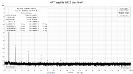
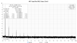
THD vs. output voltage for idle current 41mA, 105mA and 182mA:
"Overbiased" is again the best at lower power, then equal to other settings. So, the optimum bias myth does not work for the complete power amplifier.
THD vs. frequency at 5W, it is nicely flat:
Again we can play with 3D derivative dVout/dVin:
and compare it with measure results. The strictly defined optimum point does not exist, but we can choose an area with smallest deviations in linearity. It may be also seen that heavy overbiasing leads to increased distortion by low order harmonics. So, to me it seems that small "overbiasing" leads to best results in most cases of class AB amplifiers. More pairs automatically lead to better results.
Last edited:
But the results clearly show lower distortion at higher bias specifically at lower power, which is the most audible part of perceived sound and any higher level signal must pass the low level as well. And all is measured with one pair. Textbook simulations are simplified and valid for only an isolated pair of output devices.The 23mV is correct for BJT.
If you have a proof - and as a proof I consider measurements on a real complete amplifier- please post it to make a proof for "optimum bias".
From this we can say 23mV bias should be the lowest we would go.
And that chosing a higher bias than that would not hurt. On the contrary it can benefit.
And that chosing a higher bias than that would not hurt. On the contrary it can benefit.
Newbie alert (please be gentle).
I do understand this is about particular topology and specific circuit. What about sliding bias (vintage Technics, JVC, pioneer etc.'s Class AA, New class A,non switching amplifier) ? Do they have more distortion compared to typical class ab topology ?
Probably to broad a question 🙏
I do understand this is about particular topology and specific circuit. What about sliding bias (vintage Technics, JVC, pioneer etc.'s Class AA, New class A,non switching amplifier) ? Do they have more distortion compared to typical class ab topology ?
Probably to broad a question 🙏
I am not able to reply the question on topologies I did not have a chance to investigate myself.
Generally - I thought that DIY standed for Do It Yourself. At least it was a goal, decades ago. What I can se now is rather SIY - simulate it yourself. Simulators are great tools, however I am not happy of this trend. Almost anyone can sit on the arm chair and run the simulator.
Generally - I thought that DIY standed for Do It Yourself. At least it was a goal, decades ago. What I can se now is rather SIY - simulate it yourself. Simulators are great tools, however I am not happy of this trend. Almost anyone can sit on the arm chair and run the simulator.
Quite some time ago (2017) I did some distortion tests using the QA 401 on a high power, high loop gain EF3 power amplifier (6 pairs of OP devices) over a range of powers from about 10 or 20 watts up to full power (240 W) in to 8 ohms and found the optimum OPS bias per output pair was very wide and flat from around 25mA all the way up to about 80mA. The amplifier in question (a Model 1721) did 7ppm into 8 ohms at 200W output, which was as low as I could measure with the QA401. I use 0.33-ohm emitter degeneration resistors. Unfortunately, I did not keep a record of my tests, but I concluded at the time that the Oliver voltage wasn't a hard and fast rule, and you can consequently bias the amplifier OPS over a wide range and still get good results. I did not measure at very low powers, but at these levels, the measurement is dominated by the test gear noise floor/resolution anyway.
I think it's important to ensure the bias current is reasonably stable over temperature, especially if you are going for a low output stage bias like Self appears to advocate. Pegging low-OPS bias currents and making sure they don't drop off to the point of inadvertently causing class B crossover distortion over the temperature and power operating envelope is more challenging to control than the 35 to 70mA I usually use.
YMMV 🙂
@Hiten - This board has quite a few threads on bias regulators and non-switching amplifiers.
@PMA - The lopsidedness is a sign of running the drivers and/or predrivers in class AB. I suspect the amplifier has the emitter resistors connected to the output node rather than to the other side.
BTW, I learned a great deal about distortion mechanisms by writing simulators. I wish everyone had that experience.
@Bonsai - That we can't agree on the number (20/22/23/26mV) is a consequence of the optimum bias being dependent on signal amplitude. This can be seen by solving Ebers-Moll numerically. 26mV is just a small-signal approximation.
I agree that bias stability is extremely important. Talking about optimum bias does not make sense when the actual bias can vary over a 2:1 or even 4:1 range.
Ed
I still can not justify to buy an audio analyzer. Thus, although I have built a bunch of amplifiers in the past of decades, I have no way to verify the THD. That why I heavily rely on the simulation.Generally - I thought that DIY standed for Do It Yourself.
I have shown only lower power recently. There might be complaints on Gm doubling at higher power. Now, please see measurements up to the clipping point. As PSU is only +/-25V, the Vpp and power is limited.

But again, "overbiased" is better, up to maximum power (36W/4R7).
But again, "overbiased" is better, up to maximum power (36W/4R7).
Thanks Andrew. Just one comment, as you can see, the small difference at lower power is visible.Quite some time ago (2017) I did some distortion tests using the QA 401 on a high power, high loop gain EF3 power amplifier (6 pairs of OP devices) over a range of powers from about 10 or 20 watts up to full power (240 W) in to 8 ohms and found the optimum OPS bias per output pair was very wide and flat from around 25mA all the way up to about 80mA. The amplifier in question (a Model 1721) did 7ppm into 8 ohms at 200W output, which was as low as I could measure with the QA401. I use 0.33-ohm emitter degeneration resistors. Unfortunately, I did not keep a record of my tests, but I concluded at the time that the Oliver voltage wasn't a hard and fast rule, and you can consequently bias the amplifier OPS over a wide range and still get good results. I did not measure at very low powers, but at these levels, the measurement is dominated by the test gear noise floor/resolution anyway.
Higher order harmonics go away with higher idle current, it is absolutely evident.I did not measure at very low powers, but at these levels, the measurement is dominated by the test gear noise floor/resolution anyway.
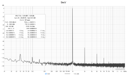
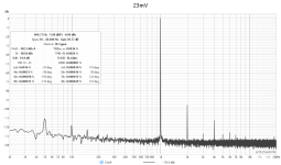
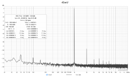
(5V/4R7, Re=0R22) 9mV, 23mV and 45mV bias voltage across 0R22 Re.
I can measure reliably down to and below -120dBr at 2V and with noise below the amp noise, if necessary. Higher idle current means class A operation up to higher voltage level, switching/crossover distortion disappears. we want to prevent sudden slope changes in the transfer function and they are present at low idle current and most pronounced at low power. At high power, the idle current almost does not matter and crossover nonlinearities are masked by the high signal level.
- Home
- Amplifiers
- Solid State
- Optimal bias in push-pull EF output stage: textbooks and reality