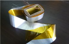
Hi, there is an amplifier around (Esoteric A100), its a PP with 4xKT88 for 90W output power. It uses a OPT with the secondary winding made with silver-coated copper foil (see attached picture)
What would be the advantage of doing that - the layers should have significant inter-layer capacitance, wouldnt that degrade performance? Any ideas or comments?
What would be the advantage of doing that - the layers should have significant inter-layer capacitance, wouldnt that degrade performance? Any ideas or comments?
Attachments
As it's the low impedance secondary winding, I wouldn't think interlayer cpacitance would be more of a problem than it is in foil speaker inductors.
But it would be a bastard to wind, unless it's also insulated.
Regards, Allen
But it would be a bastard to wind, unless it's also insulated.
Regards, Allen
Such an unusual transformer might help the advertising agency write exciting blurb?
Normally a wide foil would give low inductance but high capacitance. Winding it into a coil would seem to give higher inductance and high capacitance too. It might increase coupling slightly, since each primary turn will be nearer all secondary turns. This would reduce the leakage inductance a little. The effect would be much greater with an air-cored transformer, but an iron core concentrates the flux so that every turn is already quite tightly coupled to every other turn. I hesitate to call it a gimmick but it would be interesting to hear their explanation.
Stop Press: I have just seen their explanation and it is tight coupling, as I suspected. I would be surprised if it actually makes much difference, but at least they are not trotting out pseudo-scientific piffle.
Not a particularly good idea. The ideal tightly coupled secondary is a single layer of wire next to another single layer of wire. The coils of foil will provide distributed capacitance, distributed leakage inductance, self capacitance and self inductance out of character with what is needed for optimal coupling. And yes Allen, it would be a mess to make.
However, it might not be too bad with amorphous core, since an optimized design for that material wants no capacitive coupling and as much leakage inductance between coils of primary and secondary as possible, just to tame the FR spikes out above 50 kHz.
I have made step down transformers for ribbon speakers utilizing single turns of copper foil, interspersed with wound primary turns (the huge Red Rose system from Bo Bingsten many years ago) and foil works best in this sort of application. This is the only audio application I can think of where it is the best solution. Now, power transformers might be a different setting.
Bud
Strip is the ideal realization of a very fine layer of wire. The practical issue with wire is, everyone makes round wire. But wire gets impractical for high amperages, getting very thick, leaving lots of air, having to connect it in parallel, etc.
Strip is used often in switching supplies. If it's good enough for them, ohya, it's plenty fine for OPTs!
What I would be more concerned about is, why does it need strip? Strip is used when the winding requires only a few turns, carrying currents well over 20A. OPTs need 20-100 turns secondary and even high power outputs, at 8 ohms, need only a few amps. It's pointless for most purposes.
As far as tube circuits go, strip would actually be handy for very large filament windings. These are typically 10-30 turns, and end up being made from many strands of wire. You could make a 6.3V 20A winding no problem.
Tim
Last edited:
I suspect low secondary dcr might be a strong motivation in 0 feedback SE amplifiers in particular. The secondaries of most the transformers I use in my amp have a dcr of at least 0.5 ohms on the 8 ohm tap, and even assuming a perfect voltage source and no primary dcr the damping factor would be no higher than 16 and probably much less in the real world with primary dcr and the tube rp..
thanks a lot for your interesting comments guys!
Not sure if the amplifier in question has a feedback loop that includes the OPT - I would rather think it does not. So, the DCR of the secondary winding should play a role in this.
Would the silver coating help in any other sense than just marketing (e.g. skin effect)?
Not sure if the amplifier in question has a feedback loop that includes the OPT - I would rather think it does not. So, the DCR of the secondary winding should play a role in this.
Would the silver coating help in any other sense than just marketing (e.g. skin effect)?
Not unless you are expecting a lot of corrosion. Silver is a better conductor than copper, but not a lot better. However, I think I am right in saying that silver oxide is quite a good conductor whereas copper oxide is much poorer (and is really a semicondutor?).
Remember, the net effective resistance of the secondary includes the transformed resistance of the primary too so there is little point in treating only one of them with silver.
Remember, the net effective resistance of the secondary includes the transformed resistance of the primary too so there is little point in treating only one of them with silver.
You have it exactly right DF96, unless the copper coating is cupric oxide, in which case it is a non conductor.
I have had it postulated to me that silver has fewer empty orbits than copper and that this indicates that a more coherent and complete E Field moment occurs when the wave form involved halts for a vector change. This would indicate a more complete retention of low level wide band information in an audio signal. I have no particular opinion about this but it might explain some of the "myth" of silver superiority in "audionervousa" activities.
I have had it postulated to me that silver has fewer empty orbits than copper and that this indicates that a more coherent and complete E Field moment occurs when the wave form involved halts for a vector change. This would indicate a more complete retention of low level wide band information in an audio signal. I have no particular opinion about this but it might explain some of the "myth" of silver superiority in "audionervousa" activities.
It's An Ecellent Idea...
...For RF xfmrs. This particular construction would serve to reduce stary capacitance (since you don't have single turns next to each other, all with slightly different potentials). This also serves to increase coil Q by reducing the resistance increase that skin effect causes.
High frequency, broadband, RF xfmrs, such as those used in "no tune" solid state RF amps, it's better even if it's harder to wind. Whether it'll make a difference at audio frequencies is questionable.
Ah, the empty orbits - now why didn't I think of that? Maybe I am still drowning in the Fermi sea?
Ah, the empty orbits - now why didn't I think of that? Maybe I am still drowning in the Fermi sea?
What is the orbit if there is no object? Contemplate this, Grasshopper.
Not as fast as with olive oil.
Anyway, the chief advantage of using foil windings is that higher current densities are achieved, so they are more suited to compact inductors or powerful field coils.
John
Anyway, the chief advantage of using foil windings is that higher current densities are achieved, so they are more suited to compact inductors or powerful field coils.
John
Last edited:
The skin depth chart shows that there may be some advantage in using a thin ribbon instead of normal wire, but we are only talking a few % at 20kHz. This is not much when you consider the variation with frequency of any loudspeaker. It would be a bit like putting especially smooth tyres on a vehicle which is only driven on dirt roads - in theory you get a smoother ride but nobody would notice!
Mmmh . . . yes . . . but you may want to extend bandpass well over (in fact reduce "in band" phase shift) for gNFB stability considerations.The skin depth chart shows that there may be some advantage in using a thin ribbon instead of normal wire, but we are only talking a few % at 20kHz.. . .
Sometimes bifilar winding is just what you need . . . easier to wind than a rectangular wire

Yves.
The least offensive way to benefit from 100% phase change free secondary wire that I know of is to use type 1 Litz lay up, utilizing #40 AWG single coat insulation magnet wire.
Also one of the most expensive ways to spend your customers money.
The audible benefits are found in retention of very small amplitude, wide band coherence, a general "ease" in portrayal of complex signals.
Bud
Also one of the most expensive ways to spend your customers money.
The audible benefits are found in retention of very small amplitude, wide band coherence, a general "ease" in portrayal of complex signals.
Bud
Anyway, the chief advantage of using foil windings is that higher current densities are achieved, so they are more suited to compact inductors or powerful field coils.
Right. More of power per volume, and per kilogramm of iron core.
- Status
- Not open for further replies.
- Home
- Amplifiers
- Tubes / Valves
- OPT with foil secondaries