Hello,
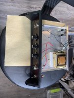
I have the opt and power transformer from this schematic. My goal is to build a Fender Champ with 6V6 output.
The issue is what to do with the 6V6 cathode as it's running through the opt secondary. Not interested in the
brilliance control or the indicator eye circuits in this drawing. The schematic is using a 6L6GB which I have but
would prefer 6V6 as I have a lot more of them.
Thanks!
Attachments
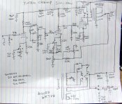
The VM circuit uses cathode feedback from the OPT secondary of the OPT to the output tube cathode. I do something similar in my SSE HiFi amp. It makes a mediocre OPT slightly less mediocre, sometimes, as it doesn't work wonders on a really crappy OPT, and it doesn't always make an improvement on a really good OPT. The circuit also develops a negative voltage for fixed bias with a resistor in series with the power transformer HV center tap. The cathode could just be tied to ground and the connection to the OPT secondary ignored, but you would still need a negative bias source.
The typical Fender Champ circuit uses cathode bias, which would be the best choice here as well since you are going to have more B+ voltage than a 6V6GT is rated for. That never stopped Leo, or me though.
It would appear that an 8 ohm speaker would get connected between the yellow and green wires, but this doesn't follow conventional color coding. You are going to use an OPT made for a 6L6GB with a 6V6GT, so if it were me, I would try all three combinations of connecting 3 wires to two speaker terminals and see which best suits your use of the amp. What works best for clean may not be the best for "cranked to 11" so a switch may be in order.
I made a few of these "Turbo Champs" back in the late 1990's. Most used a KT88 or a 6L6GC with an Allied 6K7VG power transformer resulting in about 435 volts of B+ with a 5AR4 rectifier. I used a Hammond 125CSE OPT on several and I simply connected every tap to a switch. In practice only two or three positions were useful though. Some were built with the power transformers ripped from some discarded HP audio oscillators. Some used whatever OPT that I could scrounge. A few even used the 6K6GT tubes from the HP oscillators though most of them were eventually swapped for 6V6GT's. Some even used car stereo speakers obtained when a local K-Mart closed down. No two amps were the same and none may have actually matched this schematic which was drawn from memory after the last amp was built. I probably made 10 to 15 of them over a 5 year or so period. There were a few push pull tube amps and even some solid state and chip based guitar amps too.
Attachments

Good info George! I’ve already purchased a Celestion 8 ohm speaker for it. I’m using a 1/4” jack for the connection. I may install a switch to use the other windings to try different speakers some day. Thanks!