In attach some rests published on Audioreview magazine about three trafos
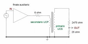
In Fig. 1 the test set
We check the trafos putting the signal from a SS amp to the secondary then measuring the results on resistive partitor.
There isn't the bias current because we haven't measured significative difference with it. I have sent the tests in other thread
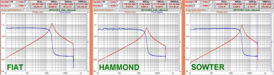
Impedances
With a new software by Fabrizio Montanucci of Audioreview is possible to see the plot of impedance vs frequencies.
The primary ( now the secondary, in this configuration) is open and the secondary ( now the primary) is connected with a nominal load ( 6 ohm for FIAT, 8 ohm for Hammond and Sowter).
In this way we can measure the effective L vs frequencies also with a little signal from primari ( secondary).
We can see that the Hammond 1627SE show an L of 8,8 H at 30Hz and 8.4 at 1000 Hz; interesting is the value at 20KHz where the capacitive components became great and this is one of the main problem of the OT trafo in general.
We can see that Sowter has the lowest value of C maybe for a better architecture.
On low end the Fiat is better than others.
The sum is that for every trafo the goal is to get the high L at low frequency and low C at high because in this way the tube we connect at the trafo can deliver the non distorted current at the Z we have choice for the project.
Regarding the resonace in theory it must be out from audio frquency but this is not possible so we can see that the peak is over 2,5 Khz for Sowter (=low L) and at 2 KHz for FIAT (=higher L).
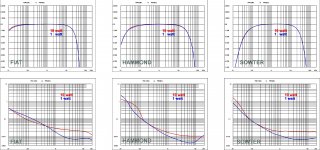
On the other tests, Freq_resp+THD_Freq at 1 watt and 10 watt
we can see that the best answer comes form FIAT ( but this is a prototype) following the Hammon is algoo quite good.
Regarding the THD vs Frequency in the low end the FIAT is fine the Hammond too but with a THD at 1,5 % at 20 Hz but it show a very good performance from 2 KHz to 20K.
Bye, for the moment
Walter
In Fig. 1 the test set
We check the trafos putting the signal from a SS amp to the secondary then measuring the results on resistive partitor.
There isn't the bias current because we haven't measured significative difference with it. I have sent the tests in other thread
Impedances
With a new software by Fabrizio Montanucci of Audioreview is possible to see the plot of impedance vs frequencies.
The primary ( now the secondary, in this configuration) is open and the secondary ( now the primary) is connected with a nominal load ( 6 ohm for FIAT, 8 ohm for Hammond and Sowter).
In this way we can measure the effective L vs frequencies also with a little signal from primari ( secondary).
We can see that the Hammond 1627SE show an L of 8,8 H at 30Hz and 8.4 at 1000 Hz; interesting is the value at 20KHz where the capacitive components became great and this is one of the main problem of the OT trafo in general.
We can see that Sowter has the lowest value of C maybe for a better architecture.
On low end the Fiat is better than others.
The sum is that for every trafo the goal is to get the high L at low frequency and low C at high because in this way the tube we connect at the trafo can deliver the non distorted current at the Z we have choice for the project.
Regarding the resonace in theory it must be out from audio frquency but this is not possible so we can see that the peak is over 2,5 Khz for Sowter (=low L) and at 2 KHz for FIAT (=higher L).
On the other tests, Freq_resp+THD_Freq at 1 watt and 10 watt
we can see that the best answer comes form FIAT ( but this is a prototype) following the Hammon is algoo quite good.
Regarding the THD vs Frequency in the low end the FIAT is fine the Hammond too but with a THD at 1,5 % at 20 Hz but it show a very good performance from 2 KHz to 20K.
Bye, for the moment
Walter
Attachments
Last edited:
Self-resonance is a bit unlucky formulated.
What I get out of this is that up to 2 kHz coupling is dominated by inductance.
Above 2 kHz the core is loosing it's effect, and coupling becomes inductive/capacitive.
HF behaviour of the transformer would be pretty similar with and without core.
What I get out of this is that up to 2 kHz coupling is dominated by inductance.
Above 2 kHz the core is loosing it's effect, and coupling becomes inductive/capacitive.
HF behaviour of the transformer would be pretty similar with and without core.
After 2 kHz became mostly capacitive as the blu line of phase says.
So, in my opinion, if the core is important the architcture of coils is more important.
In addition I am curious to understand in which way the manifacturer check the L and, in general, the performances.
I hope that the method we used in Audioreview can be adopted from them; it is easy.
Walter
So, in my opinion, if the core is important the architcture of coils is more important.
In addition I am curious to understand in which way the manifacturer check the L and, in general, the performances.
I hope that the method we used in Audioreview can be adopted from them; it is easy.
Walter
Last edited:
I am wondering if those super expensive transformers from Tango, hashimoto, AN, etc. also act like coupling capacitors as far as high frequencies are concerned. I bet they are.
What's the name of the software? Did the magazine do a review on it? If so, can we read the review?With a new software by Fabrizio Montanucci of Audioreview is possible to see the plot of impedance vs frequencies.
At the moment this sw is in a beta test but Fabrizio use it to show some test results on magazine
It use a good pc audio card and a little hardware ( a little box with two resistor and one switch) because the software subtract all residual resistance connection (Rdc of cables, contact resistence) between the of the dut under test and audio card. So the measure is effective related to the dut.
I will give you better information
Walter
I am wondering if those super expensive transformers from Tango, hashimoto, AN, etc. also act like coupling capacitors as far as high frequencies are concerned. I bet they are.
I think the answer is yes. There is some scattered writing about using an aircore transformer as tweeter amp, the last writing I remember is by Broskie.
Bi-Wire Ideas
regards, Erik
Yes, you can calculate a "self-resonance" for any transformer when you take primary inductance and winding capacitance and calculate the resonance frequency accorsing to f=1/(2*PI*SQRT(LC)). It will end up smack in the middle of the audio band. This is what you expect, because this "resonance" has to be near the middle of the passband of the transformer. It would be interesting to calculating the Q of this "resonance", at 1.5 nF capacitance (which is about what high-end transformers achieve), 28 H primary inductance and a 600 Ohms resistance, the Q of this "resonance" becomes 0.0043. This means that this "resonance" is damped into oblivion and then some more to relegate it into total insignificance.
The transformers DON'T act as coupling capacitors at any frequency, they keep acting like proper transformers up to their upper frequency limit, above which they start to act like a second order (assuming a simplistic leakage inductance-winding capacitance model) lowpass filter. The winding capacitance of the primary appears as a parallel capacitance across the primary leads. Only at very high frequencies, the inter-winding capacitance gets a low enough impedance to start acting like a coupling transformer in a typical (competently made) OPT. This typically happens somewhere in the MHz range.
The transformers DON'T act as coupling capacitors at any frequency, they keep acting like proper transformers up to their upper frequency limit, above which they start to act like a second order (assuming a simplistic leakage inductance-winding capacitance model) lowpass filter. The winding capacitance of the primary appears as a parallel capacitance across the primary leads. Only at very high frequencies, the inter-winding capacitance gets a low enough impedance to start acting like a coupling transformer in a typical (competently made) OPT. This typically happens somewhere in the MHz range.
Nobody says that the trafo acting a coupling capacitor at any freq.
The test results says that above the resonance the main aspect is capacitive, in fact also the phase switch from + (inductive) to - (capacitive).
And L drop with frequency increase.
This means that the capacitive aspect became relevant from a mid frequency due a winding charatheristics only
Walter
Walter
Last edited:
How have your determined the resistor values in the figure 3 ?In attach some rests published on Audioreview magazine about three trafos
Walter
2475R
25R
thanks
To get the a ratio 10:1 to read the test signal also with a simply audio card and proper sw, in case.
The value of 2475+25 is 2500 ohm that is a nominal load related ( in this case FIAT Trafo) to the ratio of the trafo, in his case secondary 6 ohm primary 2500 ohm, ratio is 1:20
Walter
The value of 2475+25 is 2500 ohm that is a nominal load related ( in this case FIAT Trafo) to the ratio of the trafo, in his case secondary 6 ohm primary 2500 ohm, ratio is 1:20
Walter
Last edited:
Nobody says that the trafo acting a coupling capacitor at any freq.
This is what I was referring to. Also in answer to Erik de Best's response.I am wondering if those super expensive transformers from Tango, hashimoto, AN, etc. also act like coupling capacitors as far as high frequencies are concerned. I bet they are.
The fact that above the center frequency the parallel component is capacitive and below the center frequency the parallel component is inductive is no news, but the drop in inductance, where does that come from? I think that the primary inductance doesn't drop at all, it only appears to do so because of the presence of other parallel and series components. If you measure the inductance of a parallel LCR circuit at its resonance frequency with an LCR meter, it will read zero. The inductance is not gone, it is just masked because of the presence of other components not accounted for.
This is what I was referring to. Also in answer to Erik de Best's response.
The fact that above the center frequency the parallel component is capacitive and below the center frequency the parallel component is inductive is no news, but the drop in inductance, where does that come from? I think that the primary inductance doesn't drop at all, it only appears to do so because of the presence of other parallel and series components. If you measure the inductance of a parallel LCR circuit at its resonance frequency with an LCR meter, it will read zero. The inductance is not gone, it is just masked because of the presence of other components not accounted for.
Indeed, my reply wasn't correct. I agree that the transformer is never a capacitor - I was mostly thinking about the fact that the core has less of an influence at HF and wanted to point sser2 to some existing info about that.
- Home
- Amplifiers
- Tubes / Valves
- OPT Characterization