Exactly the same modules are to be installed on 95 model too. The 95 model is even superior to 105/105D (mods point of view), as it allow a 4+4 configuration for the DAC outputs, on a stereo balanced/unbalanced stage. !05/105D it allow only a 2+2 configuration... For more infos, please PM.
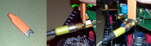
I just finished the upgrade of my PSU for AVCC-VddL/R. It will have a visual signalizing (the same one) for both charge and discharge of the large capacities used by this type of PSU. This indicator it may be (optional) mounted on the headphone connector of the player, as this output of the Oppo players are almost unused.
At Power ON, the PSU will signalize (by light) while the caps`s charging is in progress, then light off when the DAC analogue rails are at the right levels. When Power Off, the same visual indicator it will light using the energy accumulated in the caps, until completely discharging.
I do hope to have the new boards in few weeks...
I have to say that is not confirmed the statement about "no sound" when changing XLR polarity in Menu settings, while DAC outputs are 2+2 configured.
The software/firmware care about DAC chip one inverted channel (for design reasons), and compensate this when XLR is set it on Inverted.
Inverting the XLR polarity (2+2 configuration) it slightly alter somehow the soundscene configuration. For someone it may sounds different, for another ones it may not. It may also depend on the played content. For me it fit best the Normal setting.
But there is sound for both polarities...
There is a discussion in between many mod interested people, about the main power supply type to be used for Oppo players. Alternative to the original SMPS one, there is on marked a serial PSU offered by OppoMod.
Personally I have my reasons to support the Oppo designers choice for a SMPS for the digital stage of the player, while the analogue stage it use a serial type PSU.
Some others support the use of OppoMod solution for the digital stage of the Oppo players, based on their reasons.
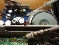
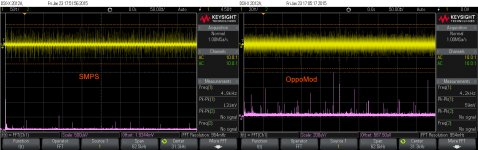
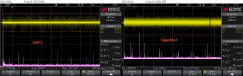
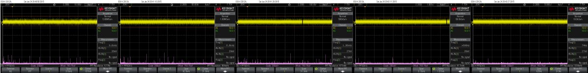
Recently I had the opportunity to get a such OppoMod PSU, and I thought to measure both at their outputs, as the picture here shows.
Please note that here is about a original SMPS unit with improved filtering.
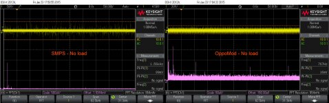
Here are the comparatives results.
As one can very easy observe, that the serial PSU it have a twice lower overall noise level on its output, than the SMPS one. But what is interesting here is the noise spectre (the FFTs), which is obvious in the favour of Oppo (improved) SMPS. Why is like this is to you to comment...
Personally I have my reasons to support the Oppo designers choice for a SMPS for the digital stage of the player, while the analogue stage it use a serial type PSU.
Some others support the use of OppoMod solution for the digital stage of the Oppo players, based on their reasons.
Recently I had the opportunity to get a such OppoMod PSU, and I thought to measure both at their outputs, as the picture here shows.
Please note that here is about a original SMPS unit with improved filtering.
Here are the comparatives results.
As one can very easy observe, that the serial PSU it have a twice lower overall noise level on its output, than the SMPS one. But what is interesting here is the noise spectre (the FFTs), which is obvious in the favour of Oppo (improved) SMPS. Why is like this is to you to comment...
Attachments
Coris, you still have a lot of work.
As can be further improved Coaxial output?
You also need to have to take on board a multi-ch plate PSB in Oppa! )))
Oppa engineers can begin to make their products correctly read this forum thread)))?
As can be further improved Coaxial output?
You also need to have to take on board a multi-ch plate PSB in Oppa! )))
Oppa engineers can begin to make their products correctly read this forum thread)))?
When you improve clocks and power supply, coaxial output is supposed to be better.
On my OPPO 105EU, another tweaker soldered 2 capacitors (Wima + unmarked) on the coaxial output. I am not able to give you more informations because work is protected (capacitor unmarked & covered by an unremovable anti emi/rfi coat).
NB: The LPM tested by Coris is tweaked by Audiocom so supposed to be better than original...
Well, I found out why the Oppomod PSU output it looks quite bad when about the spectre of noise, comparing to the original Oppo SMPS.
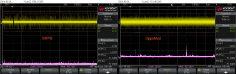
The Oppo SMPS it have an AC main filter build in, while Oppomod does not have it at all... This explain why lot of HF noises it goes through this Oppomod and are to be found on the 5V DC rail.
Oppomod it have also some important design issues for its PCB layout (long GND connections, bad components placements, and thin traces for enough high DC currents.
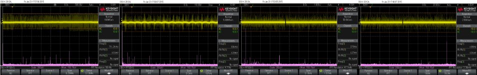
After the necessary corrections/improvements, and adding an AC main filter before the transformer, the 5v DC output it looks like in these pictures here. Not bad at all, I may say...
Overall noise level is lowered to 27mV, as the HF components of this noise are lowered quite much when using a AC main filter.
I will recommend to those who have this power supply, to use an AC main filter (enough easy to find it), placed between the AC input connector and the toroid transformer. Any kind of such filter is better than without.
The Oppo SMPS it have an AC main filter build in, while Oppomod does not have it at all... This explain why lot of HF noises it goes through this Oppomod and are to be found on the 5V DC rail.
Oppomod it have also some important design issues for its PCB layout (long GND connections, bad components placements, and thin traces for enough high DC currents.
After the necessary corrections/improvements, and adding an AC main filter before the transformer, the 5v DC output it looks like in these pictures here. Not bad at all, I may say...
Overall noise level is lowered to 27mV, as the HF components of this noise are lowered quite much when using a AC main filter.
I will recommend to those who have this power supply, to use an AC main filter (enough easy to find it), placed between the AC input connector and the toroid transformer. Any kind of such filter is better than without.
Attachments
Last edited:
Coris, you still have a lot of work.
As can be further improved Coaxial output?
You also need to have to take on board a multi-ch plate PSB in Oppa! )))
Oppa engineers can begin to make their products correctly read this forum thread)))?
I may let some mods and improvements for others too...😉
At least Oppo did a good work when they designed these players so, The modders may have a job to do it, too...😀
When you improve clocks and power supply, coaxial output is supposed to be better.
On my OPPO 105EU, another tweaker soldered 2 capacitors (Wima + unmarked) on the coaxial output. I am not able to give you more informations because work is protected (capacitor unmarked & covered by an unremovable anti emi/rfi coat).
NB: The LPM tested by Coris is tweaked by Audiocom so supposed to be better than original...
Audiocom ?! 😀😀
I have recently moded a stereo board "tweaked" before by Audiocom... They painted the whole back side of that 105 stereo board, with a kind of violin varnish, thinking that so it will sounds better... This was a part of the mod pack they offer... 😀😀😀
They are funny... is my only comment.
Coris could you pay attention to the noise in Oppomod somewhat smaller in amplitude than the SMPS. Check it out.
Indeed, the noise of serial PSU after improvements and using a AC main filtering, is much lower than the SMPS one. The only problem when using a serial PSU in this case is the heat dissipation, which is important. This dissipation it happen inside the player`s enclosure, and is no any fan to push it out... One get improvements because a lower noise level, but these improvements are cancelled by the increasing noise level, and degraded overall performances, because inside temperature increasing... So?
One may remember that both SMPS and a serial PSU are to power in this case a noisy system by its nature: the digital stage of the player...
A very quiet PSU used for a noisy system is not a very big deal in my opinion... But caring out to have a lower working temperature for the digital devices (and the analogue ones too), which really improve performances, there may be a bigger deal...
Hi Coris!
Thank you for your response.
There was two more questions.
It is important to make the best Oppa stereo sound. You Operational amplifiers used in industrial production, as well as you think maybe it makes sense to use operational amplifiers DIY from Burson Audio?
And just watch from Dexa Neutron Star, as reference? Of course they are expensive, but it can make sense to take them some ideas for your watch? Or do you think that your watch is no point more to improve?
"The Oppo SMPS it have an AC main filter build in, while Oppomod does not have it at all..."
Absolutely, that the reason why we install this kind of filters (N2 & HF):
DIY Filters - Fidelity Audio - Fidelity Audio
"After the necessary corrections/improvements"
What do you mean?
And what about noise on 15v rail?
Please have a look at JCGB amazing job concerning power noise:
http://www.hdfever.fr/forum/viewtopic.php?f=8&t=1787&start=760
Last edited:
To tekko06
I believe that Coris on the network connector 220 volts before applying power to the toroidal transformer placed LC filter. This is the usual line filter which is used for example in SMPS after the fuse.
I believe that Coris on the network connector 220 volts before applying power to the toroidal transformer placed LC filter. This is the usual line filter which is used for example in SMPS after the fuse.
"The Oppo SMPS it have an AC main filter build in, while Oppomod does not have it at all..."
Absolutely, that the reason why we install this kind of filters (N2 & HF):
DIY Filters - Fidelity Audio - Fidelity Audio
"After the necessary corrections/improvements"
What do you mean?
And what about noise on 15v rail?
Please have a look at JCGB amazing job concerning power noise:
Forum HDfever.fr - Consulter le sujet - OPPO BDP-103EU & BDP-105EU Modifiés & Tweaks
Yes, the Oppomod PSU need and external AC line filter. This is important to minimise the noises coming from outside (the AC network).
The missing AC filtering is one of the causes of an increased HF noise level (spread spectre) at the PSU output (when comparing with the Oppo SMPS).
Another source of the noises at the Oppomod outputs is the design issues of this PSU (as noticed in an above post). These design issues it can be corrected in a way, but not just enough as a right design it may perform.
There are these corrections I have made for the Oppomod PSU I have, and the results (27mV output noise) is to be seen in the above pictures. 27mV noise for a serial PSU is not bad at all! And please note that this PSU is not to be used for analogue (audio) circuits, but for a digital system/stage...
To lower even more the serial PSU output noise, one should use different regulators, or even another type of regulator devices. But I can not see any reason to work more on this task.
BTW, I can see that is a tendency of many users or "tweakers" to place ferrite bead over all the wires in a device, and especially on the hot wires coming from the serial PSU. This is just wrong! That ferrite bead placed on wires which transport important DC currents it increase, or even generate the HF noise...
The 15v rail is just not important at all. This rail it provide mainly power to a 12v regulator, which it feed further the transport device. There is a second level regulation on this already serial regulated 15v line. The adding of a line filter at the PSU input, it solve more than enough the eventual noise problems for 15v line too.
The main negative impact when about the noises from original Oppo SMPS is for the clock system of the digital stage. Please keep in mind that the clock for DACs are powered from analogue PSU, and is regulated in many levels.
My mod (battery powered clock board) it solve this issue, and use a very clean power for the main and sensitive clock oscillators in the player. So, I prefer to use the original SMPS, as it not increase the inside enclosure temperature. With some improvements, this SMPS is very good to be used for the digital stage.
But who knows, maybe I may change my mind in this respect and I will start to design one day a appropriate serial PSU (CorisMod PSU...😀 ), as an alternative to this quite primitive OppoMod one...
Last edited:
Coris!
Do you think it appropriate to apply the operational amplifiers from Burson to further improve stereo? Your opinion?
Do you think it appropriate to apply the operational amplifiers from Burson to further improve stereo? Your opinion?
Hi Coris!
Your generator Clock made galvanic isolation between outputs?
Yes, the outputs are AC coupled... Also the battery minus pole together with the board GND plane are exclusively connected to the device GND, through coax shielding, when power ON.
- Home
- Source & Line
- Digital Source
- Oppo's BDP105 - discussions, upgrading, mods...