Hi Jan, yes in fact the results I've showed are fourier analisys obtained from a .tran simulation, as you correctly quote are the results of large signal at full power, at meduim power (30W) the numbers are better !!! , soon I will post a summary of all simulations and graphics (pdf). I am aware that the real amp will not be as good as the sim, but it is indeed a good start piont.
ngspice 3 -> fourier 400000 v(4)
Fourier analysis for v(4):
No. Harmonics: 10, THD: 0.0806008 %, Gridsize: 200, Interpolation Degree: 1
Harmonic Frequency Magnitude Phase Norm. Mag Norm. Phase
-------- --------- --------- ----- --------- -----------
0 0 -0.00088048 0 0 0
1 400000 29.6109 -18.415 1 0
2 800000 0.0159347 51.5564 0.000538136 69.9717
3 1.2e+06 0.00953944 144.887 0.00032216 163.302
4 1.6e+06 0.00198606 167.63 6.70721e-05 186.045
5 2e+06 0.00765039 -111.7 0.000258364 -93.281
6 2.4e+06 0.00595414 -27.999 0.000201079 -9.5838
7 2.8e+06 0.0077691 60.4006 0.000262373 78.8159
8 3.2e+06 0.00472056 128.009 0.00015942 146.424
9 3.6e+06 0.00664317 -156.42 0.000224349 -138.01
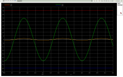
The plot shows the input signal (1.5V) in yellow and the output signal (full power ~ 55Watts) at 400KHZ, it looks very clean (make sense 0.08 THD)
Cheers
ngspice 3 -> fourier 400000 v(4)
Fourier analysis for v(4):
No. Harmonics: 10, THD: 0.0806008 %, Gridsize: 200, Interpolation Degree: 1
Harmonic Frequency Magnitude Phase Norm. Mag Norm. Phase
-------- --------- --------- ----- --------- -----------
0 0 -0.00088048 0 0 0
1 400000 29.6109 -18.415 1 0
2 800000 0.0159347 51.5564 0.000538136 69.9717
3 1.2e+06 0.00953944 144.887 0.00032216 163.302
4 1.6e+06 0.00198606 167.63 6.70721e-05 186.045
5 2e+06 0.00765039 -111.7 0.000258364 -93.281
6 2.4e+06 0.00595414 -27.999 0.000201079 -9.5838
7 2.8e+06 0.0077691 60.4006 0.000262373 78.8159
8 3.2e+06 0.00472056 128.009 0.00015942 146.424
9 3.6e+06 0.00664317 -156.42 0.000224349 -138.01
The plot shows the input signal (1.5V) in yellow and the output signal (full power ~ 55Watts) at 400KHZ, it looks very clean (make sense 0.08 THD)
Cheers
Attachments
It may work better with +-25V mosfet supply, gate protection and output zobel, hexfets are easy switched devices.
Why not just loosen the differential input stage instead of summing it back?
Why not just loosen the differential input stage instead of summing it back?
Last edited:
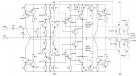
Hi Ontaba, yes the output filter correction and the protection circuits are not shown. This circuit is intended to minimize distortion (even and odd harmonics), in two ways, even harmonics by the quasi differential LPT's and odd harmonics with a complementary input LPT. I'll will update the schematic soon
Cheers
Cheers
Last draft fixed errata an some fine tuning
In this version the same superb numbers, buffer fine tuning, and clean clipping. Note that I am still not using gate stoppers, because of the negative feedback provided by the resistors attached to the sources and the low impedance buffer (I've read some papers. where authors argues that in a follower are not needed ??? question for the gurus). Simulation shows excelent stability when clipping or square wave with high dv/dt, the thermal stability of the DC offset is about +10/-10 mVolts in a range of 70°C. Anyway I will include the gate stoppers resistors in the PCB layout, and verify the stability with my old TRIO 60MHZ bandwitdh. If the circuit behaves stable I will put a wire instead.
Cheers
Arturo
Attachments
Arturo,
With numbers like this it is highly unlikely that these are realistic. Based on many experiences of turning a simmed design into hardware I would say they are MUCH too good to be true. I think others have commented on the reliability of spice device models in particular MOSFETs.
Furthermore, a spice THD sim is always a small-signal sim, and the actual input- and output levels (like your 100uV input or 30V output) are disregarded. If you want to look at actual signal levels and distortion you should do a fourier sim which is a large signal (also called transient) sim.
Let's see the fourier results.
jan didden
I agree totally -- software is ok as an indicative, that often does not represent real life in component form. I'm sure the sim cannot predict how track can cause parascetics -- additional capacitances, thermal, irregularities in supply, getting component models exact and noise. Build it and research
Hi all, yes I agree with Janneman and PhaseLockLoopy, so I'll will go back to the pure BJT version (sims are more realitics), I studied some papers about spice with MOSFETs and the software performs very poor ... but at any rate I dont dismiss the value of software, bad designs become worse in the real , no matter your experience, I am aware that sims are far from reality, what most concerns me is thermal stabilty and DC offset, (lots of experimentation before ...) thanks for your advices
Cheers
Arturo
Cheers
Arturo
Hi all, Thanks CBS240, the paper you linked was very usefull !!! the design attached use same principles showed by Dr. Hawksford but even simpler, see the shadowed area, I simmed this circuit with 5% random mistmach on components, and shows execlen offset stability (0° to 100° range), and halves (o more) THD with the modest components I have on hand. Note the the prior designs, had MANY MANY problems, and was unreal the current in the VAS, this desing overcomes all these problems.
Cheers
Arturo
Cheers
Arturo
Attachments
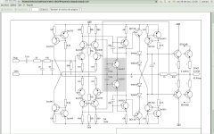
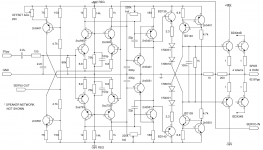
The final design
This is the final design of my audio CLASS A amplifier.
Specs.
Thermal stability +/- 5mV offset 0° - 100°
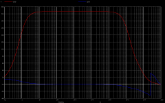
Hifi power BW of 200KHZ (THD < 0.01%) -0.3DB @ 200KHZ
Large signal Slew Rate: 57Volts/usec.
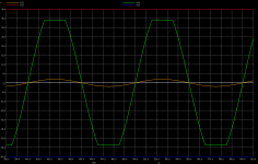
Clean Square Wave, clean clipping
At full power (60Watts RMS @ 8 OHM load)
200KHZ < 0.01%
100KHZ < 0.005%
10KHZ < 0.001%
output impedance: 0.0013 OHMS
Voltage gain: ~ 21
sensivity: max input 3Vpp, output 62.88Vpp
I am working now with the design of the PCB, so I believe that maybe in 3 or 4 months (as it is a hobby for me) it should be finished.
Cheers
Arturo
This is the final design of my audio CLASS A amplifier.
Specs.
Thermal stability +/- 5mV offset 0° - 100°
Hifi power BW of 200KHZ (THD < 0.01%) -0.3DB @ 200KHZ
Large signal Slew Rate: 57Volts/usec.
Clean Square Wave, clean clipping
At full power (60Watts RMS @ 8 OHM load)
200KHZ < 0.01%
100KHZ < 0.005%
10KHZ < 0.001%
output impedance: 0.0013 OHMS
Voltage gain: ~ 21
sensivity: max input 3Vpp, output 62.88Vpp
I am working now with the design of the PCB, so I believe that maybe in 3 or 4 months (as it is a hobby for me) it should be finished.
Cheers
Arturo
Attachments

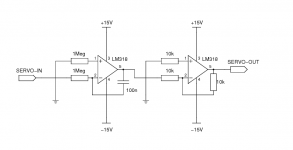
The final design with DC offset servo
Hi all,
The real final design,
OK I've heard the gurus, so this version uses a servo to avoid thermal offset drift, the rest is kwown, except for some last minute teaks, (less current in the VAS, more in CLPT's aided by the inclusion of the servo. With a carefull PCB design this thing should sound great (I hope). I do NOT RECOMMEND nobody spending $$$ with this design, until the real thing being tested (a friend has a HP spectrum analizer, and other works at a audio studio, with several amp's & sonic equipment wich offered me help). Thank's to all the wise opinions and recommendations to be aware of.
Cheers
Arturo
Attachments
- Status
- Not open for further replies.
- Home
- Amplifiers
- Solid State
- opinions