I thick their is a Furom rool about not ridiquling someone's speeling... but punkshuashun is whole nother deal.
Don't put spaces before periods, commas, colons, or ellipsus (...); always put a space after them though.
😀
Don't put spaces before periods, commas, colons, or ellipsus (...); always put a space after them though.
😀
If the info is good, I don't care how it's punctuated.
I can punctuate with the best of them, but I don't know speaker design, so I have no problem with it. 😉 😉
I'll post those measurments in a bit, but indeed it's just a little hole(3.3cm) in the baffle which I may seal permenantly if it makes designing the crossover easier.
RDV
I can punctuate with the best of them, but I don't know speaker design, so I have no problem with it. 😉 😉
I'll post those measurments in a bit, but indeed it's just a little hole(3.3cm) in the baffle which I may seal permenantly if it makes designing the crossover easier.
RDV
The internal volume is:
Height = 28.5cm
Depth = 19cm
Width = 8.4cm
With round a vent hole of 3.3cm
RDV
Height = 28.5cm
Depth = 19cm
Width = 8.4cm
With round a vent hole of 3.3cm
RDV
6.8 ohm seems to be a difficult value.
6.5 & 7 are readily available.
Which would you recommend?
3.3 ohm is however quite common.
I would imagine combining values to come up with 6.8 exactly would increase inductance even with non-inductive resistors. I say this because I could combine a 6.5 with a .33 to come up with the recommended value.
RDV
Replies to Punctuation ...
Thanks Al , I'll try that suggestion in this post .
Hey , what about that ! - so simple - as it should be - silly me !
I'm surprised I didn't find this by accident , but thanks for telling me - no-one else has ever raised the subject !
Thanks poobah - humour always helps !!
Well RDV , as you had obviously read me without too much difficulty , I have no doubt you can read Schematics which sometimes look difficult , which I'll keep in mind for a later post .
The Cabinets .
Do you mean the front is 19cm wide internally , as it wouldn't fit these 6 1/2 drivers if only 8.4cm {about 3 5/8"} - ?
Even then , multiplying the 3 dimensions gives a cabinet Volume of only 4.332 litres - that is a very small cabinet ! Is there a mistake in the digits , eg:- perhaps it is 18.4cm ?
The 3.3cm hole - I presume the baffle panel is the same 5/8" thick as you said for the cabinet walls in an earlier post ?
Yes , even short length of panel thickness determines the tuned frequency of the cabinet .
Good , and from your picture it looks like its about 2" thick .
If on both sides + top and bottom + back panel , then anywhere between 1 1/2" to 3" is fine as a start to hear your bass-mid driver's potential well enough .
Umm , being a cheap Sanyo cabinet , I ask , do the drivers fit onto the front of the baffle panel , or do they attach from behind the baffle - ie:- mounted from inside the cabinet ?
And , if on the front , are they rebated into the panel so their flanges are flat flush fit with the surface of the panel - at least for the tweeter ? , or are their flanges like a circular ridge above the flat surface ?
Flanges raised above would not a huge problem , because you can cut a surround of suitable thickness from thin wood , or cork tiles , or thick felt , or whatever , to render them flush fitted - as that will reduce diffraction effects which will become more audible to you when you have a smoother response bass-mid driver fitted .
RDV said:The internal volume is:
Height = 28.5cm
Depth = 19cm
Width = 8.4cm
With round a vent hole of 3.3cm
RDV
Do you mean the front is 19cm wide internally , as it wouldn't fit these 6 1/2 drivers if only 8.4cm {about 3 5/8"} - ?
Even then , multiplying the 3 dimensions gives a cabinet Volume of only 4.332 litres - that is a very small cabinet ! Is there a mistake in the digits , eg:- perhaps it is 18.4cm ?
The 3.3cm hole - I presume the baffle panel is the same 5/8" thick as you said for the cabinet walls in an earlier post ?
Yes , even short length of panel thickness determines the tuned frequency of the cabinet .
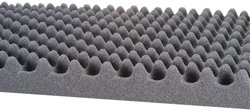
RDV said:There's also foam like this lining the entine internal enclosure.
RDV
Good , and from your picture it looks like its about 2" thick .
If on both sides + top and bottom + back panel , then anywhere between 1 1/2" to 3" is fine as a start to hear your bass-mid driver's potential well enough .
Umm , being a cheap Sanyo cabinet , I ask , do the drivers fit onto the front of the baffle panel , or do they attach from behind the baffle - ie:- mounted from inside the cabinet ?
And , if on the front , are they rebated into the panel so their flanges are flat flush fit with the surface of the panel - at least for the tweeter ? , or are their flanges like a circular ridge above the flat surface ?
Flanges raised above would not a huge problem , because you can cut a surround of suitable thickness from thin wood , or cork tiles , or thick felt , or whatever , to render them flush fitted - as that will reduce diffraction effects which will become more audible to you when you have a smoother response bass-mid driver fitted .
The resistors for the L-pad , plus one more .
7ohm is near enough if difficult to get 6.8 , but don't go less than 6.8 . I'll explain why when you get the SEAS drivers , and you may need a larger parallel resistor in the L-pad then .
6.5 + .33 is too much fuss for what here is an experiment for you to hear if approximately -6dB is what you need to match the Audax to the Goldwood , and similarly , don't worry too much about the inductance for this Parallel connected resistor for the experiment , use any cheap 10watt wirewound from a Radio Shack shop or whatever shop in your area .
If you are buying the 3.3 non-inductive via mail order , then buy two 2.7ohm/10watt also , to try if -6dB is too much .
Also , I forgot for days' ago post , buy two 8.2ohm/10watt non-inductive to try in series with the 10uF cap. across the Goldwood , as an earlier poster suggested a resistor there .
This partially reduces the amount of mid-range roll-off of the Goldwood in the 2k -3kHz region , and such R.C network is basically a Zobel also , though we do not know until measured exactly what values of R and C are needed . The R will be close to 8.2ohm and probably no larger than 10ohm , thus if no 8.2 , buy nearest value between 8ohm and 10ohm . If you already have two wirewounds in 10ohm/10watt , those will do to experiment to hear the basic change of sound , even if are not non-inductive .
When you have all in circuit :- the L-pad + the 10uF+8.2ohm Zobel + the 1uF back in parallel with the 5.6uF to tweeter , then try first with both drivers connected in the same polarity . If this does not sound better than as it is now then swap the tweeter polarity to negative .
If the treble is too dull in both polarities , replace the 3.3ohm with the 2.7ohm in the L-pad .
This is still the below optimum Goldwood driver , so do not expect a wonderful result .
Post what you hear and which combination you prefer for the resistors in the L-pad ; for the resistor in series with the 10uF as Zobel ; and which Polarity tweeter you prefer the sound in .
With this type of cross-over - including Zobel - the best listening axis should be with ears on axis to the woofer , and with the tweeter above or below {which-ever suits you stands height best} . Exact vertical axis will vary with the distance you are away from the speakers , you may prefer a little off-axis from centre of woofer in the direction of further away from the tweeter . Look at the plot of the Audax's frequency response . See how it rises in the high treble , but remains fairly flat in the 30 degrees off-axis plot . Thus , listening at a small angle off the tweeter axis gives flatter response , as well as causing the acoustic centres - the radiating points of the midrange sound - to be time/phase aligned to some better degree when you are more towards woofer axis , particually with this type of cross-over now .
Only major problem is you will hear what remains of that upper-midrange peak in the Goldwood when on-axis to the woofer . If this annoys you , I have one more experiment , but first report on your preferred Polarity connection of tweeter versus woofer .
You may hear less of that better handclaps response you reported in an earlier post that you first heard when you installed the Audax , but what I think you were hearing then was the tweeter Fs of 1k235 being driven excessively into resonance by the handclaps , as they have much sound in that area of the frequency spectrum .
If all this takes a while for you to try , then email to me via the link on the post when you have posted next , as I do not always look regularly in this forum , but do post if a correction to that 8.4cm and others in my previous post today .
Re: The Cabinets .
I have the resistors and a good poly caps on order from Madisound and will post reports on any findings.
RDV
alan-1-b said:
Do you mean the front is 19cm wide internally , as it wouldn't fit these 6 1/2 drivers if only 8.4cm {about 3 5/8"} - ?
Even then , multiplying the 3 dimensions gives a cabinet Volume of only 4.332 litres - that is a very small cabinet ! Is there a mistake in the digits , eg:- perhaps it is 18.4cm ?
The internal width is about 7.5" in inches. It is small but a 6.5" or 7" fits fine.
The 3.3cm hole - I presume the baffle panel is the same 5/8" thick as you said for the cabinet walls in an earlier post ? Yes.
Yes , even short length of panel thickness determines the tuned frequency of the cabinet .
Good , and from your picture it looks like its about 2" thick .
If on both sides + top and bottom + back panel , then anywhere between 1 1/2" to 3" is fine as a start to hear your bass-mid driver's potential well enough .
Umm , being a cheap Sanyo cabinet , I ask , do the drivers fit onto the front of the baffle panel , Yes.
or do they attach from behind the baffle - ie:- mounted from inside the cabinet ? No.
And , if on the front , are they rebated into the panel so their flanges are flat flush fit with the surface of the panel - at least for the tweeter ? , No.
or are their flanges like a circular ridge above the flat surface ? Yes.
Flanges raised above would not a huge problem , because you can cut a surround of suitable thickness from thin wood , or cork tiles , or thick felt , or whatever , to render them flush fitted - as that will reduce diffraction effects which will become more audible to you when you have a smoother response bass-mid driver fitted .
I have the resistors and a good poly caps on order from Madisound and will post reports on any findings.
RDV
Cabinet Internal Dimensions:
Height 11.25 inch
Width 7.25 inch
Depth 7.25 inch
Obviously I don't know crap about the metric system.
I got the parts from Madisound today and excitedly installed them.
Eagle resistors in the aforementioned values and replaced the cheapo electrolytics with Bennics.
I think I hear a change for the better in the high end, it seems a bit clearer and more balanced.
The mids are however still have a bit of hair because of the woofers, it's pretty easy to hear. I suppose they need a bandpass filter at that spike in their response.
I think I got my money's worth with the new parts however.
RDV
all the changes ?
That was fast delivery and installation !
Bennic caps should be OK , and as are 5% tolerence the 6.8uF shouldn't be too large if +5% .
Did you buy 6.8 , or 5.6 and use in parallel with the 1uF you already had ?
With 3,3ohm or 2.7ohm in the L-pad ?
Polarity of the tweeter ?
To be sure of this , as that green mark may indicate -ive , test for polarity :- 2 pieces of wire ; 3 alligator clips or similar ; 9volt battery .
Clip one wire to the -ive of battery and its other end to what you think is -ive of tweeter .
Clip other wire to +ive of battery .
Very very lightly touch the centre of the tweeter dome with the most sensitive part of the underside of one of your fingers - no pressure - simply touch .
Touch other end of +ive wire to what you think is +ive terminal .
If it is +ive terminal , you will feel slight pressure on your finger - it may be only very slight , so be sensitive .
If it seems less pressure then swap terminals of the tweeter and try other polarity .
When you have found +ive , you will feel the pressure reduce as you remove the wire from the terminal , BUT , if -ive , the remove will slightly increase the pressure on finger .
Do not leave battery - a DC voltage supply - connected to the tweeter , just touch one wire and remove soon after you have felt the pressure increase or decrease .
So , now , which Polarity of tweeter do you prefer , when woofer is in +ive {test the Goldwood also to be sure its marked correctly} - ??
You may hear a quiet click sound each time you make & break the battery connection to the tweeter . This will be louder when you test the woofer .
Re: all the changes ?
The Bennics are 6.8µF.
The tweeter is polarized correctly and sounds best that way as I've tried reversing them.
I used the 3.3 ohm and I like the sound fine.
As I said though, the mids are pretty blarish at that peak in the GW's response. I think a bandpass might help that. I may borrow from that article on the GW project you posted earlier as he seemed to get the most out of the GW woofer that could be gotten.
I may fill the rest of the empty space in the cabinets with polyfill(loosely) so the woofer will think they're in a bigger cabinet.
I don't have the money for the SEAS drivers for now. I've got a partially disabled wife so my income is badly compromised at the present time.
If you have an idea as for the BP/zobel values that would be very cool.
Thanks again.
RDV
alan-1-b said:That was fast delivery and installation !
Bennic caps should be OK , and as are 5% tolerence the 6.8uF shouldn't be too large if +5% .
Did you buy 6.8 , or 5.6 and use in parallel with the 1uF you already had ?
With 3,3ohm or 2.7ohm in the L-pad ?
Polarity of the tweeter ?
To be sure of this , as that green mark may indicate -ive , test for polarity :- 2 pieces of wire ; 3 alligator clips or similar ; 9volt battery .
Clip one wire to the -ive of battery and its other end to what you think is -ive of tweeter .
Clip other wire to +ive of battery .
Very very lightly touch the centre of the tweeter dome with the most sensitive part of the underside of one of your fingers - no pressure - simply touch .
Touch other end of +ive wire to what you think is +ive terminal .
If it is +ive terminal , you will feel slight pressure on your finger - it may be only very slight , so be sensitive .
If it seems less pressure then swap terminals of the tweeter and try other polarity .
When you have found +ive , you will feel the pressure reduce as you remove the wire from the terminal , BUT , if -ive , the remove will slightly increase the pressure on finger .
Do not leave battery - a DC voltage supply - connected to the tweeter , just touch one wire and remove soon after you have felt the pressure increase or decrease .
So , now , which Polarity of tweeter do you prefer , when woofer is in +ive {test the Goldwood also to be sure its marked correctly} - ??
You may hear a quiet click sound each time you make & break the battery connection to the tweeter . This will be louder when you test the woofer .
The Bennics are 6.8µF.
The tweeter is polarized correctly and sounds best that way as I've tried reversing them.
I used the 3.3 ohm and I like the sound fine.
As I said though, the mids are pretty blarish at that peak in the GW's response. I think a bandpass might help that. I may borrow from that article on the GW project you posted earlier as he seemed to get the most out of the GW woofer that could be gotten.
I may fill the rest of the empty space in the cabinets with polyfill(loosely) so the woofer will think they're in a bigger cabinet.
I don't have the money for the SEAS drivers for now. I've got a partially disabled wife so my income is badly compromised at the present time.
If you have an idea as for the BP/zobel values that would be very cool.
Thanks again.
RDV
the woofer .
It will cost you much more in parts prices to make a filter to attenuate the upper mid peak in that woofer than you paid for the woofer , plus you will have to measure it to find exactly where it is , and its amplitude and bandwidth . Owing to different voice-coil and sample variations , it will not likely be at exactly the same frequency, etc ... as the 4ohm sample that was measured . Thus it is not worth all the time and money , but better to save the money towards the better SEAS woofers .
The Dammar or Damar you asked about in an earlier post will stiffen the cone , thus there will still be a peak break-up resonance somewhere - probably higher in frequency - and the dammar is not likely to improve that sharp drop in response in the 1.2kHz region .
As it is a paper cone , and a concentric ridged design , it will be stiff in one dimension and not in another {that type of design is for woofers only , not for bass/midrange drivers} . Better would be to apply a flexible , slightly massy damping substance to the cone . Are there any "Urethane Bond" type adhesives sold in Hardware stores where you live ? ---
A clear , sticky substance , sold in small tubes .
From the picture , the cone looks to be a plain , uncoated paper substance , and the surround is described as Foam {of some sort} . What do these look like to you ?
The cone may be able to be damped some-what to reduce the amplitude of that upper mid spike .
The surrounds are foam and the paper is coated or treated with something.
I've probably gone as far as I can without spending more money.
I'll do the fill thing as that's cheap and I may actually alredy have some here from one of the wife's unfinished projects.
RDV
I've probably gone as far as I can without spending more money.
I'll do the fill thing as that's cheap and I may actually alredy have some here from one of the wife's unfinished projects.
RDV
I'll post my comments after each section in the Quote from your last post --->
:RDV said:
The Bennics are 6.8µF.
The tweeter is polarized correctly and sounds best that way as I've tried reversing them.
---> As you prefer the sound with both drivers connected in the same polarity , there is nothing else that can be done with a simple cross-over .
I used the 3.3 ohm and I like the sound fine.
---> OK , but keep the 2.7ohms as you may wish to use after my next modification suggestion .
As I said though, the mids are pretty blarish at that peak in the GW's response. I think a bandpass might help that. I may borrow from that article on the GW project you posted earlier as he seemed to get the most out of the GW woofer that could be gotten.
---> See my other post {#94} on this bandpass idea .
I may fill the rest of the empty space in the cabinets with polyfill(loosely) so the woofer will think they're in a bigger cabinet.
---> If you already have some polyfill this can be tried , but do not buy polyfill as there is better at same or not much more price :- soft Fibreglass , as used for Roofing Batts heat insulation . These can be bought from a Hardware store in several thicknesses and Grades of Density . Use simple fibreglass only batts , not the ones with metal foil stuck on one side of . Fibreglass can be handled wearing gloves , and keep it away from your eyes . As it will be in a sealed cabinet it will be quite safe once installed .
If you do not want to use fibreglass , Acousta-stuf works better than ordinary pollyfills . $9.50 from Madisound and Parts Express , and there is one other item available from Madisound for $15.00 you may wish to use if you cannot find similar elsewhere {more on this later} .
I don't have the money for the SEAS drivers for now. I've got a partially disabled wife so my income is badly compromised at the present time. If you have an idea as for the BP/zobel values that would be very cool.
---> I'll present an idea that will improve the Goldwood a little so you can use it whilst you are saving for SEAS , but it will not be a Miracle , only a small improvement .
For Zobel , I hope you have the 8.2ohm {or 10ohm} + 10uF cap connected in parallel with the Goldwood . You can listen to hear if any further improvement with your 5.6uF bipolar connected in parallel with the 10uF cap. .
For modifications .
Again , I'll post after each relevant line in the Quote , --->
---> Any Urethane Bond type adhesive available from Hardware shops in your area ?
Again , I'll post after each relevant line in the Quote , --->
RDV said:The surrounds are foam and the paper is coated or treated with something.
---> Does the paper treament look like something additional can be stuck to its surface , particually over the centre dome ?
The treatment will either be for moisture resistance , or some type of additional stiffening or damping . I am hoping that a Urethane Bond type adhesive can be applied and will remain stuck on to the surface . It is not water solvent , so it will probably stick on OK .
I've probably gone as far as I can without spending more money.
I'll do the fill thing as that's cheap and I may actually already have some here from one of the wife's unfinished projects.
---> If you have any "fill" , describe to me what it looks like , ?
Do you or your wife have any Felt ?
Soft felt , as often used as an underlayer in making women's clothes , and for soft children's toys , and sometimes by Materials' Artists .
---> Thickness - 1/16" : 2mm ; 1/8" , ?
---> Any Urethane Bond type adhesive available from Hardware shops in your area ?
The polyfill is that fluffy stuff sold at hobby shops.
---> Any Urethane Bond type adhesive available from Hardware shops in your area ? I've yet to check.
No felt around here.
RDV
---> Any Urethane Bond type adhesive available from Hardware shops in your area ? I've yet to check.
No felt around here.
RDV
Another modification possibility .
I'll post the mod. idea as soon as time , but for now , there is another mod. also possible , thus I ask :-
The cones , are they absolutely straight sided {radially} or flared slightly ?
By straight , I mean ignoring the 3 raised concentric ridges . Those ridges look as if are raised on the front - ? - and if so would not protrude above the surface of the back of the cone .
Re: Another modification possibility .
RDV
alan-1-b said:The cones , are they absolutely straight sided {radially} or flared slightly ? Flared.
By straight , I mean ignoring the 3 raised concentric ridges . Those ridges look as if are raised on the front ? Yes.
RDV
- Status
- Not open for further replies.
- Home
- Loudspeakers
- Multi-Way
- Opinions on tweeters please.