Hello! I'm restoring and upgrading an old pair of 3-way speakers. I decided to make a crossover upgrade as well since I was at it. The old one didn't sound very well. I measured the drivers and loaded the data on Xsim.
It's an old pair of Namco NSU-770 (made by Panasonic in the 70s I guess...)
It's a 12" woofer paper woofer, 2,5" paper dome midrange, 1" aluminum tweeter.
This is my try at it but it's my first time doing a 3-way.
The FR and impedance graph look pretty okay to me but when I was setting the delay the simulated curve didn't overlap perfectly with the measured one. I did my best to match as closely as possible the measured tweeter + midrange response with the simulated one.
The woofer's FR looks pretty odd, there's a big hole at around 700Hz. I guess I'll have to live with this. The phase seems okay, reversing the midrange compared to how it's now leads to a weird FR.
Do you think this design can be improved in any way?
Project files are attached.
Thank you!
Attachments
Hi. What do you mean? Usually I take a measurement of FR of the various drivers first (tweeter, midrange and woofer) one at a time, then I measure the FR of the parallel between each pair of drivers (tweeter+midrange,midrange+woofer), then I go on XSim->curve->get file and import the measurement of the parallel of the tweeter and midrange.
I wire the midrange and tweeter in parallel on the schematic without any crossover and adjust the mod delay value until the system response matches the one I imported.
I wire the midrange and tweeter in parallel on the schematic without any crossover and adjust the mod delay value until the system response matches the one I imported.

It would help lazy people like me if you showed the individual driver responses (with crossover) in your frequency response plot. If those all look reasonable, no need for me to download files. I rarely go to that trouble for a quick look at what someone has going on.
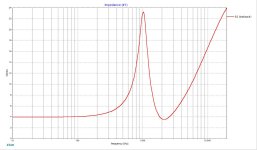
Can you measure the impedance of the midrange alone (no crossover)? Or are those in your Xsim model? Your high-pass on the midrange may be a bit low depending on the driver resonance (looks like it's around 600 Hz going by its frequency response without crossover). If you only listen at lower levels it may be OK, but at high levels may lead to high distortion if you're pushing the midrange too far.
Did you do a nearfield measurement of the woofer to confirm the dip in its measured response is real? Floor bounce can easily contaminate a measurement and produce a result like that. A description of your measurement setup (distance from microphone to speaker, microphone to nearest reflecting surfaces, gating, etc.) would be useful also.
Did you do a nearfield measurement of the woofer to confirm the dip in its measured response is real? Floor bounce can easily contaminate a measurement and produce a result like that. A description of your measurement setup (distance from microphone to speaker, microphone to nearest reflecting surfaces, gating, etc.) would be useful also.
The impedance is in the Xsim model already, I measured the impedance and frequency response of each driver... The midrange is about 13dB down at Fs (572Hz). I agree I would like it lower but given the hole in the frequency response of the woofer there's not much I can do without heavily sacrificing linearity. I doubt this system will ever play extremely loud (it's already very efficient and it will be hooked up to a 30w RMS receiver).
Regarding the dip, it is indeed real. Haven't done any true nearfield measurements but moving the mic around at various distances (and angles) confirmed that it was indeed the woofer.

This is a drawing (not in scale) of my measurement setup and room. The speaker baffle is 37cm (15") wide

This is the midrange's impedance curve
Regarding the dip, it is indeed real. Haven't done any true nearfield measurements but moving the mic around at various distances (and angles) confirmed that it was indeed the woofer.
This is a drawing (not in scale) of my measurement setup and room. The speaker baffle is 37cm (15") wide
This is the midrange's impedance curve
Attachments
Just to make absolutely sure, I would take a measurement with the microphone at about 1/4 inch away from the woofer cone. Having it as close to the floor as you did during measurement would worry me given your gating/distances, and a nearfield test is quick. That dip has such an impact on the overall design that I'd want to be certain about it.
You could also elevate the speaker (sit it in a chair or in a chair on a box) if you want to repeat your 1 meter-ish measurement. If you can get the speaker up to about 3 feet from the floor, then decrease your gating to about 6 ms, some other response variations might smooth out as well. That's worth a quick check, even if you don't do the full measurement series.
A couple other ideas/questions:
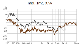
A distortion test of the midrange will help you figure out where its limits are. If you use something like 2-3 volts, you should be able to test it down pretty low without risking damage. I'd still only run the test down to about 400 Hz though until you're sure how it's behaving. Placing the microphone close to the driver will help improve accuracy (as long as you don't exceed the microphone's limits - typically around 120 dB). Longer term, I'd also run a higher power distortion check with the crossover in place. 96 dB at 1 meter is a pretty common higher power test for the full speaker/crossover.
What was the crossover like in the original speaker? I'm curious how far you are from the original cross points and what you're trying to improve.
You could also elevate the speaker (sit it in a chair or in a chair on a box) if you want to repeat your 1 meter-ish measurement. If you can get the speaker up to about 3 feet from the floor, then decrease your gating to about 6 ms, some other response variations might smooth out as well. That's worth a quick check, even if you don't do the full measurement series.
A couple other ideas/questions:
A distortion test of the midrange will help you figure out where its limits are. If you use something like 2-3 volts, you should be able to test it down pretty low without risking damage. I'd still only run the test down to about 400 Hz though until you're sure how it's behaving. Placing the microphone close to the driver will help improve accuracy (as long as you don't exceed the microphone's limits - typically around 120 dB). Longer term, I'd also run a higher power distortion check with the crossover in place. 96 dB at 1 meter is a pretty common higher power test for the full speaker/crossover.
What was the crossover like in the original speaker? I'm curious how far you are from the original cross points and what you're trying to improve.
Thank you, now we know you are not capturing time in your measurements.Hi. What do you mean? Usually I take a measurement of FR of the various drivers first (tweeter, midrange and woofer) one at a time, then I measure the FR of the parallel between each pair of drivers (tweeter+midrange,midrange+woofer), then I go on XSim->curve->get file and import the measurement of the parallel of the tweeter and midrange.
I wire the midrange and tweeter in parallel on the schematic without any crossover and adjust the mod delay value until the system response matches the one I imported.
This is a sensitive procedure which should be done carefully. I agree with mattstat that your gating is not helpful, and fixing that should make your job easier.
I always do a quick near field measurement, just to get an idea what I have got.
You do so many mistakes measuring in a small room, you should know what you do wrong. At least get the measuring object up from the ground. About half the room hight works best for me.
Consider replacing the mid driver with some low priced FR, it may be the weakest and worst part in your speaker, often only used as a filler. Do not expect too much thought in the construction and quality of the parts used inside such an old low cost speaker.
Glueing in some braces, without wasting too much volume, helps in most cases with the bass.
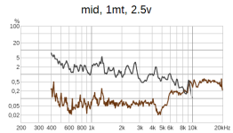
Thank you. I took the measurements again as you suggested me. I could only elevate the speaker about 50cm from the ground (20 inches). The dip in the woofer response is indeed there, even in the nearfield response. On the bright side, even at 2.5v (checked it with my oscilloscope) the midrange doesn't seems to be struggling too bad, the distortion starts rising only slightly above 400hz.
I gated all the responses to 6ms, and applied 1/3 octave smoothing. I'm also attaching the mdat file.
In the distortion graphs, the brown line is the noise floor (lower at 2.5v because I had to decrease the microphone gain)
I gated all the responses to 6ms, and applied 1/3 octave smoothing. I'm also attaching the mdat file.
In the distortion graphs, the brown line is the noise floor (lower at 2.5v because I had to decrease the microphone gain)
Attachments
-
Drivers 2.mdat4.2 MB · Views: 49
-
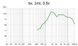 tw, 1mt, 0.5v.png5.3 KB · Views: 61
 -
 wf, 1mt, 0.5v.png5.7 KB · Views: 49
 -
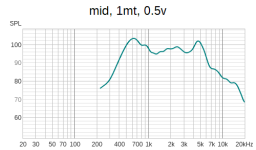 mid, 1mt, 0.5v.png5.6 KB · Views: 49
 -
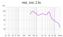 mid, 1mt, 2.5v.png5.2 KB · Views: 51
 -
 wf, 1cm, 0.5v.png6.6 KB · Views: 52
 -
 mid, 1mt, 0.5v DIST.png12 KB · Views: 50
 -
 mid, 1mt, 2.5v DIST.png10.7 KB · Views: 44
Also, I was able to take a picture of the original crossover. I was also able to set correctly the path delay on Xsim using the new measurements.
This is the original crossover:

And this is how it models on Xsim (absolute horror!!!):

To be honest, I'm not too surprised because it sounded exactly like that. It was very shouty and I could hear that the tweeter was not too happy about the crossover when raising the volume. The impedance looks scary.
This is the original crossover:
And this is how it models on Xsim (absolute horror!!!):
To be honest, I'm not too surprised because it sounded exactly like that. It was very shouty and I could hear that the tweeter was not too happy about the crossover when raising the volume. The impedance looks scary.
Forgot to answer, the build quality is pretty good. The box is braced internally, and very "dead" to the knuckle test. It is made with 2,5cm (1") particle board, veneered with real wood. Front panel is 3cm thick. It is lined with fiberglass on all sides (yes I did make sure not to breathe any in).I always do a quick near field measurement, just to get an idea what I have got.
You do so many mistakes measuring in a small room, you should know what you do wrong. At least get the measuring object up from the ground. About half the room hight works best for me.
Consider replacing the mid driver with some low priced FR, it may be the weakest and worst part in your speaker, often only used as a filler. Do not expect too much thought in the construction and quality of the parts used inside such an old low cost speaker.
Glueing in some braces, without wasting too much volume, helps in most cases with the bass.
The drivers all have pretty beefy magnets, and the woofer has a rubber surround and a very thick basket. The voice coil looks to be a 38mm one at least from the outside. The tweeter has a thick metal faceplate (very heavy). The midrange has a nice waveguide on it. Honestly all the components seem pretty good to me for such an old speaker.
This is how it looks. The attenuators still work even if they're a bit noisy and probably need some cleaning, but I may still bypass them. Ignore the wires as I added those when i was doing the measurements.

I think I'm going with this design. I've managed to make all the drivers in phase, the tweeter is nicely protected by that 3rd order and I can also salvage the big inductors from the existing crossover. They all have decent ESR, between 0.6ohm and 0.3ohm!
With your build the midrange dominates the whole sound of the box. I hope you like it's sound.
The unusual construction over it is an acoustic lens and equalizer for the mid, seems to be the solution for some problems it has. It should be meant to reduce beaming somehow and give some controled sound radiation. Interesting to know if that really works. I fear not.
I never saw such a large cup over the cone. (maybe inside a compression driver with some phantasy)
Just try to imagine what such a construction, reflecting all the sound waves, will do.
Maybe measure with and without it, if removeable. For an experiment, take some other speaker and place something similar over it. That can give you an idea what happens.
You get used even to the worst sounding speakers after some time. Always reset your hearing with a known, neutral speaker to counter that effect.
If you still got the second, old crossover, listen A-B to both speakers. You can switch your amp/ receiver to mono or feed it a mono (CD?) signal, then use the balance to switch between old and new crossover.
If you measure the bare chassis, maybe try to do it outside, Your whole simulation relies on that data.
You could even do it on a balcony, pointing away from the house, with the microphone on an extention (don't loose it!).
The mid by itself sound pretty nice, it measures quite well too... Panasonic also used those in their Technics SB500 speakers. It can't be taken off, it's welded with the basket and magnet assembly.
I already have other speakers - better and more modern ones, but I like these ones because of how they looked and because they're extremely efficient!
Sadly I can't measure outside, I live in a flat and I have very little space.
I will update the thread once I get the parts for the new crossover!
I already have other speakers - better and more modern ones, but I like these ones because of how they looked and because they're extremely efficient!
Sadly I can't measure outside, I live in a flat and I have very little space.
I will update the thread once I get the parts for the new crossover!
Hello everyone! I got the parts and installed the new crossover. These are the measurements:
On-axis with the tweeter, speaker placed on the floor.

On axis with the tweeter, speaker placed on a chair:

"Off-axis", speaker on the floor, microphone perpendicular to the baffle, at 110cm height (resembling how you would actually listen to this speaker).

These are all IN ROOM measurements, with no gating, taken at 1m distance from the speaker, in the middle of the room.
How does it sound?
The bass is very smooth and extended. They do very well with dynamics and they can get really loud with my TDA7297 lunchbox amp I use for testing, but they're somewhat bright.
I think this could be fixed if I padded down a bit more the midrange and tweeter. Seems like there's not enough BSC. However, these speakers will probably placed near a wall given how big they are (and how small typical Italian houses are) and so the response will look something like this:

As soon as I placed them near the wall, they sounded GOOD like, they are now a completely different speaker compared to before.
Overall, I got quite lucky because, while I was not expecting that much bass drop off caused by the baffle step, they still turned out great for my intended use (near a wall).
I probably didn't notice it when I was making the crossover because the gating prevented me from seeing those frequencies and by how much they were dropping off. Lesson learned, I will probably just use ungated measurements for the woofer the next time I make a speaker with such a large baffle.
On-axis with the tweeter, speaker placed on the floor.
On axis with the tweeter, speaker placed on a chair:
"Off-axis", speaker on the floor, microphone perpendicular to the baffle, at 110cm height (resembling how you would actually listen to this speaker).
These are all IN ROOM measurements, with no gating, taken at 1m distance from the speaker, in the middle of the room.
How does it sound?
The bass is very smooth and extended. They do very well with dynamics and they can get really loud with my TDA7297 lunchbox amp I use for testing, but they're somewhat bright.
I think this could be fixed if I padded down a bit more the midrange and tweeter. Seems like there's not enough BSC. However, these speakers will probably placed near a wall given how big they are (and how small typical Italian houses are) and so the response will look something like this:
As soon as I placed them near the wall, they sounded GOOD like, they are now a completely different speaker compared to before.
Overall, I got quite lucky because, while I was not expecting that much bass drop off caused by the baffle step, they still turned out great for my intended use (near a wall).
I probably didn't notice it when I was making the crossover because the gating prevented me from seeing those frequencies and by how much they were dropping off. Lesson learned, I will probably just use ungated measurements for the woofer the next time I make a speaker with such a large baffle.
- Home
- Loudspeakers
- Multi-Way
- Opinion on three way crossover - and path delay