
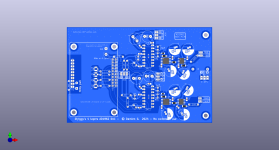
I tried to do so. As one can see, no ground on the 4 mm circa between the output of the dac and the inverted pin... it is perhaps even too much (but the ground pin of that dac chip is just the next sided one, so signal can find a short return path away from the PS ground btw.The best way to select the cap is to get the DAC to output a square wave. Any capacitance from the op-amp summing junction to ground is going to cause overshoot on a square wave. The cap across the feedback resistor can then be adjusted for max square wave fidelity. Unfortunately, even if you know the DAC output capacitance, you probably won’t know the layout parasitic capacitance. Therefore you have to do this on the actual final PCB layout. Additionally, keep any ground plane well away from the summing junction as this will cause problems as well.
Edit : the name Extinction DR(for dead rooster) is a pun story to give a stupid name to the pcb as some do 🤓
Attachments
Last edited:
If I were to design a circuit like this, I would choose some odd order for the reconstruction filter and then use this capacitor to make the first-order section (realize the filter's negative real pole).
I was assuming an ordinary unity-gain-stable op-amp here.
Regarding small resistors, for voltage followers, some op-amp datasheets recommend using small resistors either in series with the input or in the feedback or both. Those are then either meant as base stoppers or to limit the current flowing through the input protection diodes when there is a sudden voltage step at the input. That second reason doesn't apply here because the DAC output current is limited anyway, but a base stopper may be needed, depending on the op-amp design.
Base stoppers are our 'secret art' in some places when working with beasts with 15GHz GBW. (opamp!) Usually low ohm values are already sufficient. But I don't think such a situation should be encountered in audio.. even if working with ADA4899.
On the other hand, series resistance increase total noise by converting input current noise into additional voltage noise.
Which are the opamps in I/V position that You like, Iggy? I am curious. I know about the opa828, and we share the enthusiasm.. one factor could be that being a fet input opamp, it has better tolerance for input stage overload which had just been mentioned here.
It also has high slew rate capability, because of it's tricky input stage.
About the capacitor parallel to Rfeedback: I join the sceptics about it's rule as a compensation cap for stability and noise peaking. The typical audio value is much higher.
Instead, that capacitor plays a role in extending the low input impedance range at the -In node. Apart from defining the dominant filter pole. And helps with slewing.
But the input noise density of the opa, I wonder how much is the current noise generated by such dac ic we play with. Any current noise will be seen as voltage noise at the output as well ? And here I wonder how much is important the own current noise density of the inverting input pin. It is not clear to me as I am not technician sided.
We have not many choice with op amp. We always add the op861 which has something between 6 to 13 Z input in emitter input mode. I do not much focus on SR as I am not sure it is so important above a minimum, but much more settling time... And the opa861 is so so (while frankly with a little of work on PS and decoupling caps it sounds terrific in my ref DAC which is Rogic pcb based. THD is also not very good as some noticed, input emitter current noise is 17 pA; but we certainly focus too much on noise when working with redbook and 16 bits IC maybe ? And in this spirit I found the op1656 to be nice to my ears as a singleI/V opamp for 16/44 materials I mostly own.
What audio values do you mean about audio and feedback limiting bandwidth cap ? Not sure I understand what you mean after.... Noise peaking it shows at the output you mean ? But what about RF noise without it and the peaking at the end of the opa bandwidth if we do not low pass it ? (I mean in transimpedance task).
Last edited:
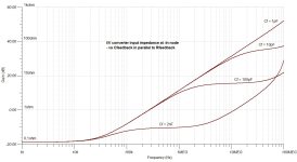
"Instead, that capacitor plays a role in extending the low input impedance range at the -In node. "
Here it is a demonstration of this:
In a circuit configured as TIA, the Cf parallel to Rf is changed from 2nF (a ~ usual value) downwards until 1pF. ~10pF would be a usual noise peaking /stability compensation value..
With increasing feedback capacitance, the impedance at the -In node stays low for a more extended frequency range.
Attachments
Thanks, very instructive. I would not go for less than 20 pF cause layout, stray capacitance, contaminents (pollution, moisture, ?). Btw I wonder here if the gnd should not be removed bellow the Rf and cF too to put a return trace close but not bellow. OK greater area ground loop but less stray risks.
Some noticed a too much big negative effect on sound when you climb too much with cF, indeed it is often I have seen 2 nF with the op828 for instance.
Some noticed a too much big negative effect on sound when you climb too much with cF, indeed it is often I have seen 2 nF with the op828 for instance.
- Home
- Source & Line
- Analog Line Level
- Operational amplifiers and feedback loop : low pass decoupling capacitor : which frequency ?