Member
Joined 2009
Paid Member
Then is a good option E180F to drive 300b ?
Works great also as an ordinary RC-coupled driver.
Attachments
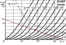
Attached is the plot of the conditions at the input of E180F at full output power.
Blue trace is cathode (at 2.15 V) and green is g1. The minimum g1-voltage is more than 0.5 V, so no problem is likely.
And if the grid current were a problem, the operating point can be shifted with 180 ohms cathode resistor to a place where the minimum g1-voltage is more than 0.77 V.
Actually this could be optimum, since the THD is decreased a bit.
And even more; with 1k the minimum g1-voltage is > 1 V.
With 1k, the anode current is still 12.3 mA.
Attachments

The R loaded, R//C biased E180F is good and simple solution...if you like "old style" tone.
The distortion not too low (for example over 0.4% at 150Vpp -this is about A1 region limit of this schematic), the driver output impedance is high, and increasing in HF region (below 100Hz).
Rout (without coupling capacitor):
3.9k 10Hz
2.95k 20Hz
2.3k 1kHz...100kHz
CCS loaded and LED biased schematic has lower (about 0.15% at 150Vpp) THD, and consistent output impedance (about 300R) in the whole 10Hz..100kHz region.
CCS loaded and LED biased schematic has lower (about 0.15% at 150Vpp) THD, and consistent output impedance (about 300R) in the whole 10Hz..100kHz region.
An example/reference of this would be useful to see. Without it, is difficult to comment.
Especially how the output impedance drop from 3k of RC-coupled to one tenth (300 ohms) with CCS and LED-bias.
Last edited:
An example/reference of this would be useful to see.
Try it.
Attachments
Last edited:
Yes, that circuit will have low output impedance, but the output is not from the tube (as I assumed). It is buffered by a FET.
That circuit will surely outperform any tube-only-circuit, like the mu-follower with NFET I posted earlier.
But what is a surprise (to some), is that the RC-coupled circuit will give more linear outcome with 300B than an E180F with a CCS.
That circuit will surely outperform any tube-only-circuit, like the mu-follower with NFET I posted earlier.
But what is a surprise (to some), is that the RC-coupled circuit will give more linear outcome with 300B than an E180F with a CCS.
- Status
- Not open for further replies.
- Home
- Amplifiers
- Tubes / Valves
- Operation point for E180F tube