An interesting design. Very compact for an open baffle and at modest cost. Congratulations on your acheivement so far. I wonder if you tried simulating the bass woofer on the same crossover leg as the woofer/mid, placing it after the filter for D2. This might result in fewer filter parts for D1. Or perhaps the bass response you are getting from D2 requires the steeper filter slope you have for D1.
Last edited:
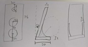
Would you be so kind to provide the baffle dimensions please?
Thank you
of cause. All measures are in cm. I guess, the conversion devider (devisor?) to inch is something around 2.5 (i.e. cm devided by 2.5 approximates inch, I guess).
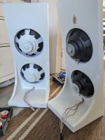
I wasn't able to find 4 cm thick MDF so I glued 2 sheets of 2 cm thick MDF together. The roundish sidewings are (obviously) for helping with bass as well as for structural strength. The wings are just 2 cm thick.
The tilt backwards wasn't a design choice actually. On my draft baffle I tried several tilts and ended up with a better bass result for a tilted baffle compared to a dead straight baffle. Considering the small height of the speakers, the 15 deg tilt is acceptable. For my room size, the angle isn't too steap to throw the tweeters out of focus.
Attachments
An interesting design. Very compact for an open baffle and at modest cost. Congratulations on your acheivement so far. I wonder if you tried simulating the bass woofer on the same crossover leg as the woofer/mid, placing it after the filter for D2. This might result in fewer filter parts for D1. Or perhaps the bass response you are getting from D2 requires the steeper filter slope you have for D1.
Maybe. When I simulate the crossover with vituixCAD2, I don't get any drastically different results when I put D1 after the D2 filter. However, I'd bet, in real life the speaker performs quite differently, vituix obviously isn't made for simulating open baffle crossovers. For a future revision I'll start with the filter for the broad range woofer and try to add the bass woofer after the broad range.
isn't made for simulating open baffle crossovers.
Crossover simulation is perfectly universal for any concept. Several open baffle speakers designed with it.
Nice looking OB design.
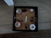
The crossover spacing looks decent but keep in mind inductor placement/orientation to avoid crosstalk.
Make sure all connections are physically well connected/twisted before appplying solder, so the solder only seals the connection and keeps it in place. and use heat shrink to seal all open ends to avoid corrosion as copper oxidation is not conductive.
External crossovers are a good thing, make a cabinet/box for it and mount your crossover board on vibration isolating mounts inside it.
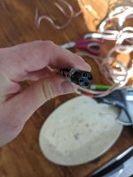
As for your cabling from crossover to speakers. as you want only one and in cotton.
Buy cotton sleeves with the propers I.D, pull each cable for woofer/tweet/mid through one, wrap it in emi shielding tape, shielding heat shrink or similar to insulate each separate signal. Use another larger cotton tube ouside and pull them all through it.
And add at least a tech flex tubing, in a decorative color /pattern of your choice. or similar outside it, optionally another large EMI shielding tube before the last layer.
And fixture it on the backside of the OB make. Take out each cable and use a reduced diameter sleeve after splitting one off to the side or however you choose to lead them in place, with a heat shrink over each split and seam to make it appear elegant.
Placement of coils in crossover networks
Anyways a nice design and keep it up )
The crossover spacing looks decent but keep in mind inductor placement/orientation to avoid crosstalk.
Make sure all connections are physically well connected/twisted before appplying solder, so the solder only seals the connection and keeps it in place. and use heat shrink to seal all open ends to avoid corrosion as copper oxidation is not conductive.
External crossovers are a good thing, make a cabinet/box for it and mount your crossover board on vibration isolating mounts inside it.
As for your cabling from crossover to speakers. as you want only one and in cotton.
Buy cotton sleeves with the propers I.D, pull each cable for woofer/tweet/mid through one, wrap it in emi shielding tape, shielding heat shrink or similar to insulate each separate signal. Use another larger cotton tube ouside and pull them all through it.
And add at least a tech flex tubing, in a decorative color /pattern of your choice. or similar outside it, optionally another large EMI shielding tube before the last layer.
And fixture it on the backside of the OB make. Take out each cable and use a reduced diameter sleeve after splitting one off to the side or however you choose to lead them in place, with a heat shrink over each split and seam to make it appear elegant.
Placement of coils in crossover networks
Anyways a nice design and keep it up )
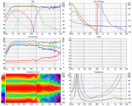
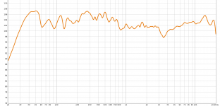
I solved my audio driver issue on my laptop today, so I measured. This is no standardized measurement, however, better than nothing. I put the speaker on a stool, and placed the mic on tweeter level at a distance of .5 m (due to the rather small room I'm in, 1 m seemed to be quite a lot).
Attachments

To me, due possibly to mic placement that second plot looks as though you had directivity issues at the upper crossover and above, making it difficult to judge how good the crossover is. Possibly relative phase issues affecting the measured response too.
Are you using the second channel as a timing reference? If you are then you can begin exploring why the crossover isn't working.
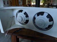
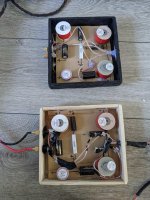
Progress. The cossover got its box, the driver cables are hidden, the drivers are fixed and sealed, and there's a 3m long cable connecting the speaker with the crossover.
See the video: Open Baffle Speakers | Work is Almost Done - LinuxRocks PeerTube
See the video: Open Baffle Speakers | Work is Almost Done - LinuxRocks PeerTube
Attachments
Last edited:
Last edited:
- Home
- Loudspeakers
- Multi-Way
- Open Baffle Speakers by Irkiosan