Hello
I was trying to create a very simple "JFET matcher" when I stumbled upon this problem which I have now solved, but I think will also be of benefit to others who simulate op-amps.
It seems that most op-amp SPICE models use the Boyle model which simplifies the op-amp so it may be simulated quickly. However those models make an assumption that both the power rails are referenced to ground and the output pin of the op-amp is also referenced to ground in all these models.
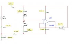
As a result very basic simulations using just an op-amp and 3 resistors will fail very badly. I have attached a diagram showing the absurdity of the simulation.
Trying to find a solution I came across AN-138 which describes this basic problem in detail. I then looked into the list of op-amps and the OP-42 series and some other op-amps are using this new macro simulation method described in AN-138.
************************************
On the attached diagram you can see the error: there are 10 mA entering the op-amp at its output pin and "magically" disappearing". Those 10 mA then re-appear at the ground node...
This very serious simulation error will happen with TL082, TL072, LM833, MC33072, NE5532 - basically all the most common op-amps used in audio circuits.
To see the problem completely go away use OP42, and I presume anything from Analog Devices. In addition the LM4562 simulates better than the TL072/LM833/NE5532 in this regard - but its model is not the one described in AN-138 so it still has 700uA magically disappearing as well.
I was trying to create a very simple "JFET matcher" when I stumbled upon this problem which I have now solved, but I think will also be of benefit to others who simulate op-amps.
It seems that most op-amp SPICE models use the Boyle model which simplifies the op-amp so it may be simulated quickly. However those models make an assumption that both the power rails are referenced to ground and the output pin of the op-amp is also referenced to ground in all these models.
As a result very basic simulations using just an op-amp and 3 resistors will fail very badly. I have attached a diagram showing the absurdity of the simulation.
Trying to find a solution I came across AN-138 which describes this basic problem in detail. I then looked into the list of op-amps and the OP-42 series and some other op-amps are using this new macro simulation method described in AN-138.
************************************
On the attached diagram you can see the error: there are 10 mA entering the op-amp at its output pin and "magically" disappearing". Those 10 mA then re-appear at the ground node...
This very serious simulation error will happen with TL082, TL072, LM833, MC33072, NE5532 - basically all the most common op-amps used in audio circuits.
To see the problem completely go away use OP42, and I presume anything from Analog Devices. In addition the LM4562 simulates better than the TL072/LM833/NE5532 in this regard - but its model is not the one described in AN-138 so it still has 700uA magically disappearing as well.
Attachments
It is easy to see if your opamp model has this problem. If you open de model file, check if there are any nodes 0, which is the global simulator ground node. If there is, you've got the problem!
jan didden
jan didden
It's disappointing that the macromodel improvements described in that Application Note are still largely ignored over 20 years after publication. (I'm inclined to say that Mark Alexander published much of that information even before PMI was acquired by Analog Devices, but can't find a reference older than the A/D App Note so I may be mistaken. I believe there is also a Burr-Brown Application Note pointing out many of the same problems, but not presenting the general, comprehensive solution that Alexander shows in AN-138.)
Many years ago I converted some Boyle-style macromodels to the Alexander-style. It wasn't a trivial task, but not beyond the skills I'd expect of a new Electrical Engineering graduate. A significant problem I recall is that many of the simulation models published by even well-respected manufacturers are very poorly commented, so the models require significant reverse-engineering before they can be converted. Even from that perspective I don't understand why major IC companies haven't used a few summer-hires, or co-op students to create models with more up-to-date performance.
Dale
I thought that just renaming the internal node 0 in the model to like 999 and bringing it to the outside would fix it. The extra pin could be grounded in the app circuit but for floating operation it could be connected to anything.
That is something anybody can do.
Would that not fix it?
jan
That is something anybody can do.
Would that not fix it?
jan
Assuming the Vin+ and Vin- pins have negligible bias currents, the currents on the remaining 3 pins of the op-amp should match up. If you introduce an extra pin, the opamp's output pin would then use that extra pin for current return, and not one of the supply rails as it should. If you left that extra pin unconnected then would anything work?
As an example, how would you simulate an opamp drawing in 1 mA on the + rail pin, 10 mA from the output pin and 11 mA on the - rail pin?
As an example, how would you simulate an opamp drawing in 1 mA on the + rail pin, 10 mA from the output pin and 11 mA on the - rail pin?
Assuming the Vin+ and Vin- pins have negligible bias currents, the currents on the remaining 3 pins of the op-amp should match up. If you introduce an extra pin, the opamp's output pin would then use that extra pin for current return, and not one of the supply rails as it should. If you left that extra pin unconnected then would anything work?
As an example, how would you simulate an opamp drawing in 1 mA on the + rail pin, 10 mA from the output pin and 11 mA on the - rail pin?
Well the ground return current that normally would flow in/out the ground node would now flow in/out the 999 node. It's the SAME node just another number. If that node is grounded in the circuit, there's no difference.
If you wanted to bootstrap the supply from say the output of a signal following amp. you'd connect that bootstrap point to the 999 node.
It would then absorb/source the current from the 999 node just as in a real circuit it would absorb/source the supply mid- or reference point, no?
jan
not "just like" because output stage Class AB output currents switch from rail to rail
some internal pole-zero modeling stages could be at node 0 for conveinence, possible convergence improvement but any interface to the op amp pins should be properly handled with appropriate floating controlled sources
but input parasitics, compensation C really are connected to the the supply pins, and the models should just do it right
Last edited:
- Status
- Not open for further replies.
- Home
- Design & Build
- Software Tools
- Opamps and ground