Hello everyone,
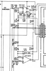
I made an attemp last days to replace an old NJM2068 opamp from my Denon PRA-1500 preamp, with some newer (an better sounding) opamps like the LT1028 , but the problem now is that the new opamp is running hot, too hot to touch, tough it seems to work fine. I also tried NE5534 which runs normally. I attached also the part of the schematic that was modified.
Any suggestions would be well appreciated.
Attachments
Last edited:
http://140.120.11.1/prophys/ael/File/Datasheet/lt1028.pdf
Looking at the schematic, the first thing I noticed was the voltage supply of +/-17.2 V. So I looked at the product sheet and maximum specs are as follows:
-55C to 105C +/- 22 V
105C to 125C +/- 16V
which I guess are typical specs. If your op amp is running too hot to touch it is surely being run past its absolute maximum voltage rating. While there are many other things that could cause your problem (but since it is unity gain stable they shouldn't), if you really want to run this chip, you might try knocking the voltage down a few volts. Or you could find a chip that runs fine in the circuit.
Try to put a 0.1uF film cap or good quality stacked ceramic from PIN4 to PIN7 of the LT1028 as close as you can. This Opamp is much faster then the one you used before and the heat is a clear sign of oscillation. Maybe you have to play also with the compensation cap over the feedback resistor.
Try to put a 0.1uF film cap or good quality stacked ceramic from PIN4 to PIN7 of the LT1028 as close as you can. This Opamp is much faster then the one you used before and the heat is a clear sign of oscillation. Maybe you have to play also with the compensation cap over the feedback resistor.
This is true.
LT1028 is not the easiest to get stable at lower gains.
It is a very good opamp. Especially for low noise and Phono RIAA amplifiers.
But personally I would not use LT1028 for 'normal' gains applications.
Joachim Gerhard's advice is probably the correct.
To try and tame the opamp and get it stable.
You may find hints about this, among the Applications Information
in the datasheet: http://cds.linear.com/docs/Datasheet/1028fa.pdf
Thanks for the answers.
measured supply voltage is around +/- 16V so it is fits the specs (-55C to 105C +/- 22 V).
I also thoght about the fact the opamps are oscillating. I will try out the solution with the 0.1uF caps.
To Gerhard: do you mean Pin 4 and Pin 8 (across the supply rails) ?
What other opamps would be appropiate using in this case?
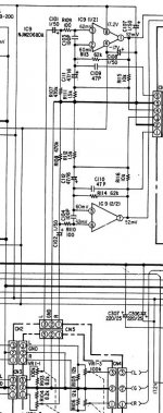
I doubt that a 5534 worked since it's a single and the schematic shows a dual. It's hard to tell the purpose of this op amp from the schematic but I'd bet it's running the optoisolator that is part of the bias circuit. Is the entire amp running hot? If so, put the original back, there's nothing to be gained by changing it since it's not in the signal path.
The NJM2068 is a dual op amp and the LT1028 is a single. Lots of the pin functions do not match.
Sorry, I have to come with some explanations: I use two LT1028 chips through an adapter (double so-8 to dip).
Hello again,
I made the modifications suggested early on in this thread: putting a 0.1 cap over the supply rails, changing the compensation capacitor, but the opamp doesn't seem to get cooler. What is the purpose of the C112/C111 capacitors from the schematic? Could these affect the oscillation of the opamp's?
I made the modifications suggested early on in this thread: putting a 0.1 cap over the supply rails, changing the compensation capacitor, but the opamp doesn't seem to get cooler. What is the purpose of the C112/C111 capacitors from the schematic? Could these affect the oscillation of the opamp's?
Sorry, I have to come with some explanations: I use two LT1028 chips through an adapter (double so-8 to dip).
An adapter? I suspect that this adapter can affect stability by virtue of making the leads longer, which can reduce the effectiveness of the bypass cap at higher frequency. Layout is very important with high speed devices, and the 0.1 uF cap belongs soldered right to the pins of the chip on the other side of the board.
deepthrob said
It's hard to tell the purpose of this op amp from the schematic but I'd bet it's running the optoisolator that is part of the bias circuit. Is the entire amp running hot? If so, put the original back, there's nothing to be gained by changing it since it's not in the signal path
If in fact this chip is not in the signal path, there is nothing to be gained by switching it. I use 741s all the time in control, delay, and sense circuits. They work, they're cheap and locally available, and they do not affect the sound because the signal does not pass through them. In fact, I don't like using op amps in the signal path except in a power amp or headphone amp. Before the preamp out, I prefer a class A circuit.
An adapter? I suspect that this adapter can affect stability by virtue of making the leads longer, which can reduce the effectiveness of the bypass cap at higher frequency. Layout is very important with high speed devices, and the 0.1 uF cap belongs soldered right to the pins of the chip on the other side of the board.
deepthrob said
If in fact this chip is not in the signal path, there is nothing to be gained by switching it. I use 741s all the time in control, delay, and sense circuits. They work, they're cheap and locally available, and they do not affect the sound because the signal does not pass through them. In fact, I don't like using op amps in the signal path except in a power amp or headphone amp. Before the preamp out, I prefer a class A circuit.
In the attachement you can see that the signal to the op amp comes directly from the volume potentiometer, so the chip stays in the signal path, and so has effect on the sound quality.
The adapter I'm using is the same as the BrownDog adapter:
Single to Dual Op-Amp Adapter by BrownDog
Attachments
r2rein, its ok to put in a word or two of your own, and not just quote what was posted just before yours
Very interesting and handy device. I still think it might make the leads too long for some sensitive circuits. However, you could solder the bypass cap directly on the device, as close as possible to the chip, and it might make the difference.
Since you're switching around pinouts anyway, have you ever considered using discrete op amps? There are many commercial devices available to replace op amps in an existing circuit. I have never used such a device, but I do find the concept intrigueing and probably useful. While expensive, many of them are dedicated to audio circuits and using them would circumvent what I dislike the most about using op amps in audio circuits: Class B and Class A-B circuitry. Check it out for yourself. Google
Since you're switching around pinouts anyway, have you ever considered using discrete op amps? There are many commercial devices available to replace op amps in an existing circuit. I have never used such a device, but I do find the concept intrigueing and probably useful. While expensive, many of them are dedicated to audio circuits and using them would circumvent what I dislike the most about using op amps in audio circuits: Class B and Class A-B circuitry. Check it out for yourself. Google
- Status
- Not open for further replies.
- Home
- Amplifiers
- Solid State
- Opamp runnig hot