I realise this is a basic topic and has been covered many times, but I have not been able to find a definitive answer.
Many opamp datasheets calls for a small capacitor at the pin of the opamp in addition to the larger capacitors at the power supply, and apparently so does many experienced designer.
However, when I simulate such arrangement on something like PSUD2, the result will always be horrible. And I am aware of the discussion on detrimental effect of adding a film capacitor across large electrolytic capacitor on power supply decoupling, especially when the distance of the capacitors are far apart (inductance).
My question is, am I confusing these separate topics together?
The reason I am asking is, recently I built a simple single stage non inverting opamp preamp. I have the the power supply capacitor (2x47µF) after the regulator mounted close to the opamp, at about 1 cm away. The I think it is oscillating (it hisses quite badly). My guess is it has to do with the power supply decoupling, otherwise I am quite stumped on how can something so simple go so wrong.
The opamp used is OPA2132, which has a reputation on being well behaved. But I ended up swapping it for LT1358 as it seems to be a tiny bit more stable.
psud2 is for power supply, at the source end.
You are referring to decoupling at the receiver end. Quite different.
You are referring to decoupling at the receiver end. Quite different.
Perhaps post a circuit of the preamp. You shouldn't hear any obvious "hiss" with any line stage op amp "gain block" (I'm assuming it is line level and not a phono stage)
psud2 is for power supply, at the source end.
You are referring to decoupling at the receiver end. Quite different.
Please enlighten me. Say if I have a 100µF capacitor on the output of a power supply, and I put a 0.1µF capacitor across it. I suppose it is a bad idea. But if I put this capacitor further down the line at the pin of the opamp, how is it different? Wouldn't it be worse off because of the longer distance?
But btw, I tied a 47nF film cap on the pin (not soldered), it motorboats like crazy.
Perhaps post a circuit of the preamp. You shouldn't hear any obvious "hiss" with any line stage op amp "gain block" (I'm assuming it is line level and not a phono stage)
It is a line level.
Say this basic non inverting arrangement:
An externally hosted image should be here but it was not working when we last tested it.
My components value are as follows:
C1 - nothing
R1 - 590kΩ (before it it has a 50kΩ potentiometer)
R2 - 1.4kΩ
R3 - 18kΩ
R4 - 10kΩ
R5 - nothing (I tried 22Ω with same result)
The resistor values are that way because those are what I happen to have on hand.
From the datasheets, they are usually quite specific in saying that the 0.1uF bypass capacitors should be as close to the power supply pins of the opamp as possible.
It is different because of the distance, which adds resistance and inductance. This lowers the frequency and Q of any resonance.Navyblue said:But if I put this capacitor further down the line at the pin of the opamp, how is it different? Wouldn't it be worse off because of the longer distance?
People often speak of 'bypass' when they add an extra cap. Remember, the big cap does not need a bypass - but the circuit might need more decoupling (especially at HF). Think 'decouple', not 'bypass'. The aim is to keep HF circuit loops as small as possible, not to 'improve' the big cap.
It is different because of the distance, which adds resistance and inductance. This lowers the frequency and Q of any resonance.
People often speak of 'bypass' when they add an extra cap. Remember, the big cap does not need a bypass - but the circuit might need more decoupling (especially at HF). Think 'decouple', not 'bypass'. The aim is to keep HF circuit loops as small as possible, not to 'improve' the big cap.
Which reminds me of this.
I suppose this is a bad idea? I tried simulating this and it's really bad. But people seem to swear that this is an improvement. I have a chip amp project down the pipeline but that is another topic. I have read the arguments I am leaning towards my simulation result, and Nelson Pass' PSU tend to have no such thing, and he seems to know what he is doing.
So what you are saying is, if I mount the 100nF cap on the PSU board, it will ring badly. But if I mount it on the amp board, it won't ring? While resistance lowers Q, won't inductance increases Q?
Last edited:
The circuit in post 4 is fine. R2L can be shorted, it does nothing. For decoupling the opamp a small electroylitic (say 4.7 or 10uf 50v) soldered on the board directly across pins 4 and 8 should work well.
There should be no audible hiss from that circuit.
"But btw, I tied a 47nF film cap on the pin (not soldered), it motorboats like crazy
Not sure what you mean by that but touching either pin 4 or pin 8 should have zero audible effect.
There should be no audible hiss from that circuit.
"But btw, I tied a 47nF film cap on the pin (not soldered), it motorboats like crazy
Not sure what you mean by that but touching either pin 4 or pin 8 should have zero audible effect.
Not sure what you mean by that but touching either pin 4 or pin 8 should have zero audible effect.
I have a a 47nF cap across pin 4 and ground, and another across pin 8 and ground. It certainly worsens it. And if it matters, there were 2x47µF PSU cap 1 cm away from it.
It sounds like you have something amiss somewhere if its behaving like this. If there is any doubt over stability due to rail decoupling then a single cap across 4 and 8 stops it dead.
The only things I can think of are,
1) If adding caps from supply to ground causes something odd to happen then look carefully at the layout and wiring scheme. In theory, if there is noise on a rail, then adding a cap from that rail to ground injects that noise into the ground. If ground were truly a point of "zero" impedance and the same all over that wouldn't matter, but its not.
2) If the opamp is oscillating, then again this probably comes down to layout and wiring/grounding. You could try adding a 22pf to 100pf cap across R3L to see if that stops the "hiss". An OPA2134 should be rock steady in the circuit you have drawn.
3) If you still get nowhere then try disconnecting the supplies and try it on two 9 volt batteries.
I'll need some time to chew on what you have said. But here are a few more bits of info that may or may not be relevant.
- The opamp is OPA2132 (not OPA2134)
- The noise is kind of like a wide band white noise
- The opamp is socketted, and the circuit is built point to point on a perf board
- I swapped the opamp for LT1358, this opamp seem to make the least noise, but the noise is more like a motorboat noise
- I tried other opamps, LT1208, LT1459, OPA2107, but they make even more noises
The power supply is a 2 stage LM317/LM337 bipolar supply. Out of the rectifier I got about ±29V. The first regulator stage is set to about ±20V, the second stage is set to about ±15V. One of the reason I do that is because the voltage of the transformer is too high and I worry about too much heat dissipation on the regulator.
The final capacitor on the PSU is 2x47µF on each rail, mounted about 1 cm from the opamp and about 5 cm from the regulator. In my earlier version, I used 2x220µF on each rail. I didn't do much careful assessment, I only listen to it through headphone and I didn't hear anything out of the ordinary. I took those caps out because I needed them for something else.
I tried a 4.7µF cap across pin 4 and 8, no difference.
As for lay out, here is the top side.
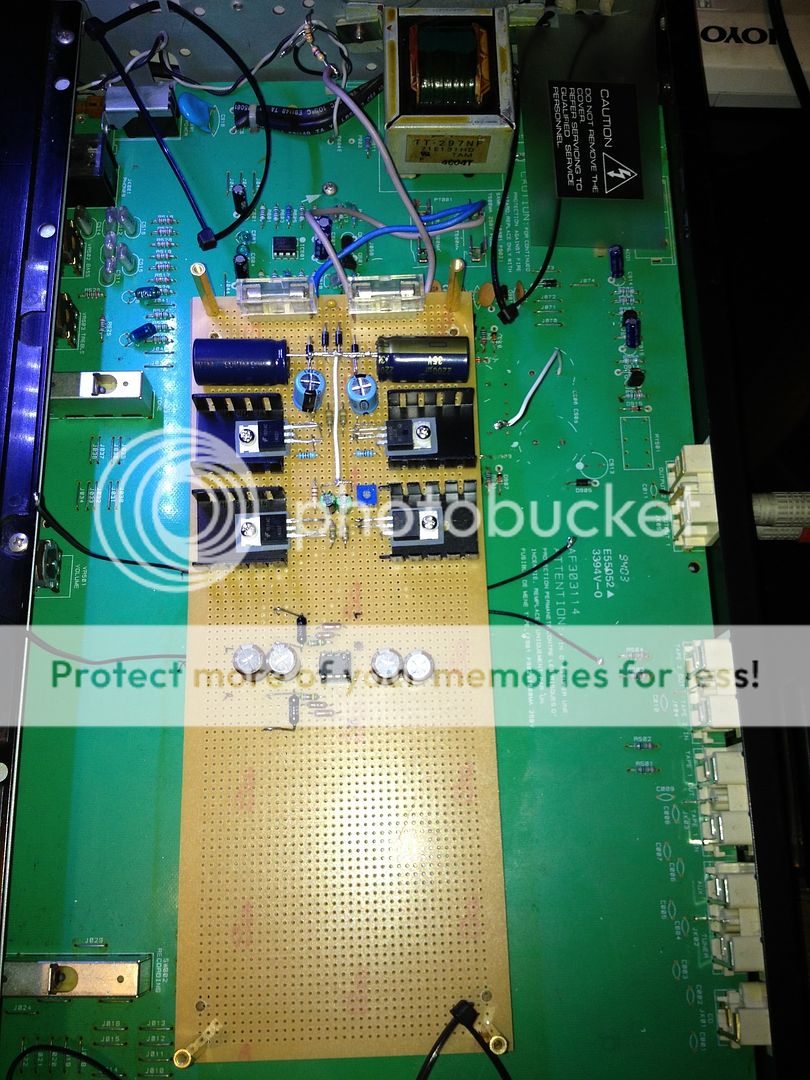
Bottom side. White wires are ground, black wires are supply rails.
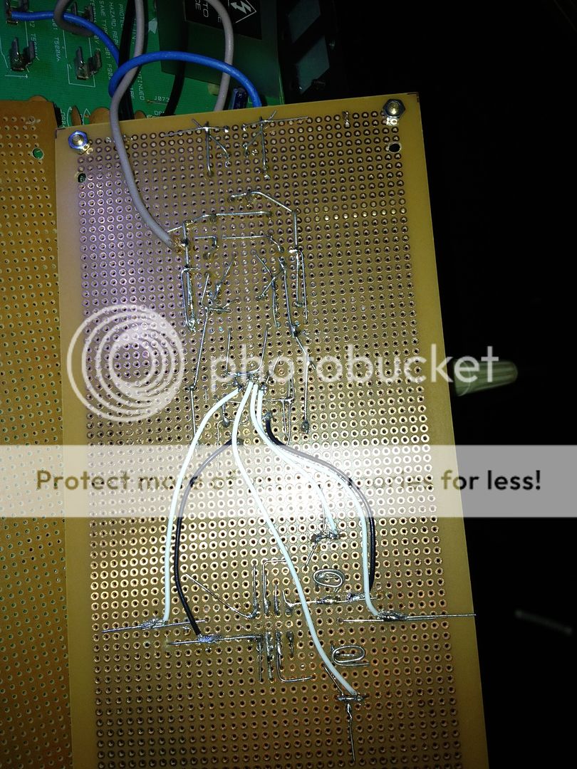
As you can see, I am building this on an old preamp. I tap the input, output and ground from the existing board underneath. I can see that the grounding may be less than optimal. So I disconnected the input, so the only thing connected to the ground plane is the output ground and the PSU ground, no difference.
As for lay out, here is the top side.
Bottom side. White wires are ground, black wires are supply rails.
As you can see, I am building this on an old preamp. I tap the input, output and ground from the existing board underneath. I can see that the grounding may be less than optimal. So I disconnected the input, so the only thing connected to the ground plane is the output ground and the PSU ground, no difference.
You're supposed to connect 0.1uF capacitors from each power pin to ground, preferably MLCC's. I don't understand what you mean by "across pins 4 and 8", and you do not EVER use electrolytics there.
The OPA2132 is similar to the 2134 either of which are perfect for this application. This problem lies elsewhere but I really don't know what to suggest. A scope would help to see what was going on.
As you mention adding the input and output connections to points already present on the old PCB, could there be any possibility of interaction with existing circuitry such as connecting the opamp output to something present and active on the board.
Do DC voltage checks show anything amiss. There should be essentially 0.00 volts on pins 1 and 7 (the output pins).
You're supposed to connect 0.1uF capacitors from each power pin to ground, preferably MLCC's. I don't understand what you mean by "across pins 4 and 8", and you do not EVER use electrolytics there.
There's a multitude of ways to decouple a circuit, everyone has there own ideas too. A single electrolytic in practice will kill any oscillation and prove the point... if that were the issue here... but its not.
From the picture, you can see that I removed the fuse on the PCB and tap the transformer output from there. So in theory it is impossible from anything to be powered on the old PCB.
And for the signal input and output, I made sure to remove everything in their paths. I tap the input from the input cap that I removed. I tap the output from the output relay that I also removed. Although to I can check again.
Unfortunately I don't have a scope. At this point I am tempted to get a cheap NE5532 preamp kit from eBay which should work. 😀 Or build a B1 buffer with the existing PSU. But my self confidence is at a low point now that I can not get this working properly. 😀
Dirkwright,
I tried a 47nF film cap, but I will humor you and try 100nF MLCC later. 😀
100nF MLCC, no luck.
I forgot to mention, there is no DC on the input and the output.
I'll try desoldering and soldering the resistors back.
I forgot to mention, there is no DC on the input and the output.
I'll try desoldering and soldering the resistors back.
The reason I am asking is, recently I built a simple single stage non inverting opamp preamp. I have the the power supply capacitor (2x47µF) after the regulator mounted close to the opamp, at about 1 cm away. The I think it is oscillating (it hisses quite badly). My guess is it has to do with the power supply decoupling, otherwise I am quite stumped on how can something so simple go so wrong.
The opamp used is OPA2132, which has a reputation on being well behaved. But I ended up swapping it for LT1358 as it seems to be a tiny bit more stable.
Stop guessing!!!!
You don't even know for sure that it's oscillating. You have to use a high frequency scope to see that for sure. Another clue would be that the opamp gets really hot.
You can't figure out a solution until you are certain of the problem.
100nF MLCC, no luck.
I forgot to mention, there is no DC on the input and the output.
I'll try desoldering and soldering the resistors back.
If you're too cheap to buy the proper parts then you can't expect to get good results.
- Status
- Not open for further replies.
- Home
- Source & Line
- Analog Line Level
- Opamp power bypass