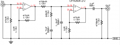
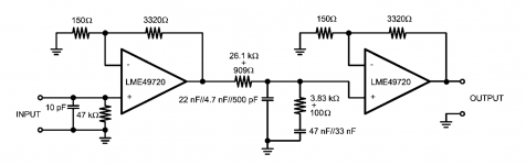
I'm just beginning to step my toe into the murky waters of phono stage design, and I've noticed there can be considerable variation among simple opamp-based passive RIAA designs in the series resistor value, with the pursuant changes in the other RC components. Attached are a couple of examples.
While the opamps used in each schematic have some differences -- input voltage noise among them -- they both are capable of driving low impedance loads with low distortion.
Why would a designer choose one approach over the other?
My apologies -- I'm certain this has been asked and answered many times before, but I can't seem to find or discern an answer
gtrmkr
Attachments
Last edited:
The first stage will generate most of the amplifier noise.
Reduce the NFB upper and lower to as low as the opamp can drive.
Try 22r & 1k0
It may work at even lower values.
Reduce the NFB upper and lower to as low as the opamp can drive.
Try 22r & 1k0
It may work at even lower values.
2nd option looks better. But some components are missing:
- a series resistor between the second opamp and output (100R)
- bypass capacitors at + and - Vcc to GND (.1uF ceramic)
There will be also some DC at the output, so a series capacitor could also be useful.
- a series resistor between the second opamp and output (100R)
- bypass capacitors at + and - Vcc to GND (.1uF ceramic)
There will be also some DC at the output, so a series capacitor could also be useful.
Last edited:
First circuit looks like it does not work.
Why does it look like it will not work ?
For some reason the 1k resistor is missing its symbol from the circuit. So, no, as shown it won't work.
What exactly is your question. Apart from differing component values, both topologies are exactly the same.Edited and corrected, I think. Schematics should show up now. Thanks!
gtrmkr
Gain of the first circuit one is a bit high, the second a bit low, but that's all a matter of selecting the right values fitting your needs.
Passive RIAA with op-amps= poor overload.
True, but with an OPA2604 with high rail voltages which will go a long way to improving overload margin.
The way the circuit is drawn, however, with a 470k build-out resistor (R1 in Lipshitz) it will also be very noisy.
For some reason the 1k resistor is missing its symbol from the circuit. So, no, as shown it won't work.
So it is. Silly me, I was looking at the wrong diagram.
Thanks 🙂
Why would a designer choose one approach over the other?
Hard to say. The only excuse for the high impedance network is the belief that a particular opamp sounds better into higher impedance loads. At some stage, a long time ago this was perhaps true.
Personally i do not like the subjective effect of high resistance in series with the signal. My current opamp riaa has no such resistor at all.
- Status
- Not open for further replies.
- Home
- Source & Line
- Analogue Source
- Opamp Passive RIAA questions